Hello,
I have a few questions before I buy an IOTaWatt.
Is a CT more accurate/sensitive when its rated capacity is closest to that of the circuit breaker, or will physical sizes affect sensitivity?
E.g. if I have a 20AMP breaker is the 20AMP CT best or is there a benefit of going the next size up.
I have not looked at my meter box yet. I suspect I have some 25AMP breakers with loads that will rarely exceed 10 amps and I am trying to decide between SCT-006-000 and SCT-013-000.
What happens if the load goes over the CTs rated capacity?
What happens if there is a power spike, does the IOTaWatt get harmed?
I ask as I use to have a WattsOn power monitor. It had three input channels and each time an electrician flipped the main breaker the input blew. After three electrician visits, there were no more working channels.
Finally is there a way of recording temperature from one of the IOTaWatt inputs?
It would be good to see the effect of outdoor temperature on power consumption.
Will installing the IOTaWatt in my steel meter box block the WiFI?
Will the temperature in the meter box cause problems in summer?
The meter box gets direct sunlight, the Wattson did not have any problems.
I will let the experts answer many of your questions in specific detail, but I can share my experiences with the IoTaWatt device over the past three weeks of my specific install.
Like you, I also had concerns about making sure I had CTs that were rated near to the circuits I was looking at monitoring. I had a few 200A, 100A, 50A, 30A, and 20A circuits and I was looking to purchase the various sizes based on the max circuit load. @overeasy set my mind at ease by letting me know the CTs he sells are calibrated for the unit and you simply do not want to put a lower rated CT on a circuit. I do not believe a higher rated CT will affect the results of the monitor. I have 50A CTs on all my 20A, 30A, and 50A circuits and things are all good.
I can say that I have had a few power spikes or brownouts in the past and also had a few instances where I needed to cut mains power (which also cut power to the IoTaWatt), and I did not experience any issues with the device. It came back up and just kept on going. Like a Timex watch, a reference for us older folks.
I think the Temp question has been asked and I believe this is a no as the device is only designed to monitor energy. For me, I have an weather station that send its data over 433mhz to a few displays. I’m in the process of setting up a Raspberry Pi and a SDR (Software Defined Radio) USB dongle to collect the radio signal, decode it, and forward this over to my EmonCMS install. That way, I get Temp, Humid, Wind speed and direction, and rain able to be ingested into the CMS tool. I also plan on building a light meter and lightning monitor to add to this data.
Again, not official responses to your questions, but my personal observations.
I would not recommend the SCT006-000. With an IoTaWatt, you will get better results with the SCT013, just because it is better quality. Although the two samples that I have tested OK for 20A at 60Hz, different batches have been tested by others with problems as low as 15A at 50Hz. If you are looking for an economical CT at low current, the Echun ECS1050-L59E is available on AliExpress, is good to 50A, smaller than the SCT013-000 and is accurate.
Depends. Mostly you get inaccurate results. You’ll see the power drop as distortion sets in. IoTaWatt has protection diodes on all inputs to protect against over-current (or more accurately the voltage developed from the over-current), but that has limitations in the amount of power it can absorb. Better to avoid that situation.
No, the TVS (Transient Voltage Suppression) diodes mentioned above protect against that.
No, there is no temperature capability.
Yes, not to mention the potential for interference from the high-voltage wires. Better to put it in a plastic box.
Oh, the steel meter box blocking Wi-Fi makes sense. But at the same time I don’t like the idea of mounting outside of the meter box for a few reasons. I might do some tests and put a raspberry PI OW in the meter box to see how its Wi-Fi performs. Apart from that do you think it would be possible to source a different ESP8266 board with a UFL connector and make an external aerial?
I understand the compliance issues around having a UFL connector on the standard product but I thought changing the board might be possible for some end users. I suspect that this will be a common problem in some parts of the world. There is a really high percentage of dwellings in Australia that have a metal enclosure for the meters and circuit breakers.
Thank you for your help Overeasy it is appreciated
Not practical. As it is I source a special nodeMCU to comply with FCC requirements. Adding an external antenna is a compliance nightmare.
The nodeMCU has a pretty standard ESP12S module soldered on. If you are handy, you could swap it out for another with the antenna, but that would be the end of my involvement. There is a community of homebrew IoTaWatt folks out there, and they seem to do what they want, but I just can’t deviate from the current design.
Most folks with your problem add an external weatherproof external box. They are cheap enough and you can use rigid or flex plastic conduit for the CT cables. The good news is that the 1.5m cables on the Echun CTs facilitate that.
Again, the external plastic box is a better solution all around.
I have to agree with @overeasy on the US electric compliance side of things. You do not want to have something that gets flagged for not meeting standards and I a simple junction box and a piece of short conduit provides a nice and compliant solution. I know there are a few commercial systems that are placed in the box and have the ability for an external ant., just not sure if that is permitted in all states.
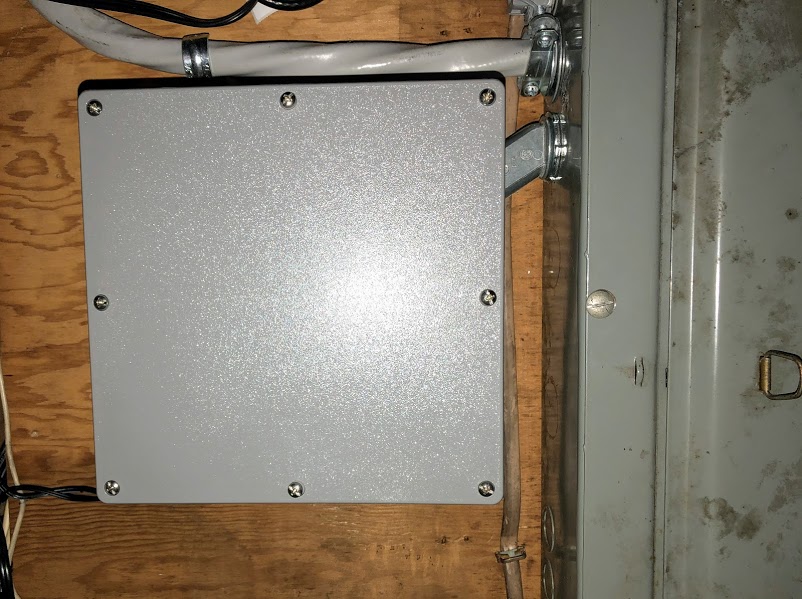
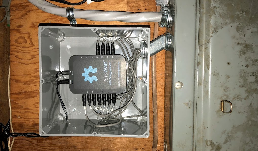
I used a 9"x9" junction box that seals and can be for inside or outside use. Not perfect, but it works and was easy to install. As you can see, there is extra room for all the connectors. I also can say that the 1.5m cables are great as I have plenty of remaining cable left in the box to make the device have a clean look. I used a 1" dia conduit and would maybe go with 1.25 or 1.5 if you plan on filling up the number pf CTs. My conduit is getting rather right for the remaining three CT in the near future.
I completely understand that Overeasy has put an awful lot of resources into the present version and that adding a UFL connector would be ludicrously expensive. I was mainly trying to figure out if hacking the IOTaWatt would be viable to gain a UFL connector. I get the impression that it is totally possible, but you are on your own if you do go down that path.
Your install looks good. Unfortunately, my meter box is located on the outside of my property with no access from the inside wall. That wall gets lots of direct sunlight in our summers and I expect that a good quality plastic enclosure would go brittle after about 5 years. Furthermore, space is limited around the meter box and the wall is covered in conduits (I have no roof cavity or subfloor cavity to run cables in).
I hope to set up a raspberry pi in my meter box to gauge the viability of wifi in the meter box. My last energy monitor ran on 433mhz and worked fine mounted in the meter box (I do understand that 433mhz working does not mean that Wi-Fi will).
Thank you for your help. I will weigh up my options and let you all know what I come up with.
Best of luck on your testing and wireless outcome as this is a great device and gives you super visibility.
I can see why you would be interested in an in-box solution. When I was looking at some of the commercial models before going with the IoTaWatt, they seemed to have issues with flush mounted boxes and ways of mounting the external ant.
I have not seen other here talk about flush mounted boxes, and I’mm surprised as I would think most newer homes would have them.
I am planning to do the same test soon in a meta meter box and I worry that my WiFi will have no signal. As a fallback I also have an Ethernet over Power line adapter (that has a WiFi AP built in) I was considering to use which will place a small WiFi access point alongside the IoTaWatt in the meter box.
Thank you bcosta, that is a good idea.
I checked my meter box area today and I have much more space than I recalled and I can put the IOTaWatt in a project box next to the meter box if need be.
I have just set up a Raspberry Pi 0W in my meter box and the pings were very encouraging. It does not guarantee that I will not have any problems but it is a good sign.
Thank you for your help everyone.
For either mounting location…
Have you considered the external powerpoint you will need for the VT? Location of powerpoint(s) and is Is your setup single/3 phase and whats your method for getting reference.
Its possible you have one in your meter box (if its old) but as far as I know this is now out of code (the old style with one mounted on a black board) and if you do any future work it will have to be removed (eg new meters/solar/etc).
At present I am still in test phase but will be make a relatively solid vented plastic box to house the 2 x iotawatt and cabling and transformers. I am hoping to get away with derived reference (and would like to run both iota watts from the single derived reference) but might end up with 3 x external weather proof plugs to supply Phase A/B/C for the VTs.
I am Newcastle NSW, if you are in the area I would love to see your setup.
I have an unused double GPO on my panel in the meter box. The meter box was overhauled when the solar went in about 4 years ago. I suspect the electricians used the code as more of a guide really, where is the rum??
I am on single phase with a 63AMP connection to the grid.
I will post my setup when I have it done. At present its in testing phase and the IotaWatt is in a temporary location (in a brick cavity, below my box.)
I have an unused double GPO on my panel in the meter box. The meter box was overhauled when the solar went in about 4 years ago. I suspect the electricians used the code as more of a guide really, where is the rum??
I am on single phase with a 63AMP connection to the grid.
I suspect you wlll be fine but your milage may vary. I don’t have GPOs for any phases in the box and there is zero space available so its going to be external.
I also interested at Ethernet version of IoTaWatt because 30-50 cm distance the energy measure and the web service/server. Pointless to use Wifi if all other are wired with Ethernet connection using UTP + RJ45.