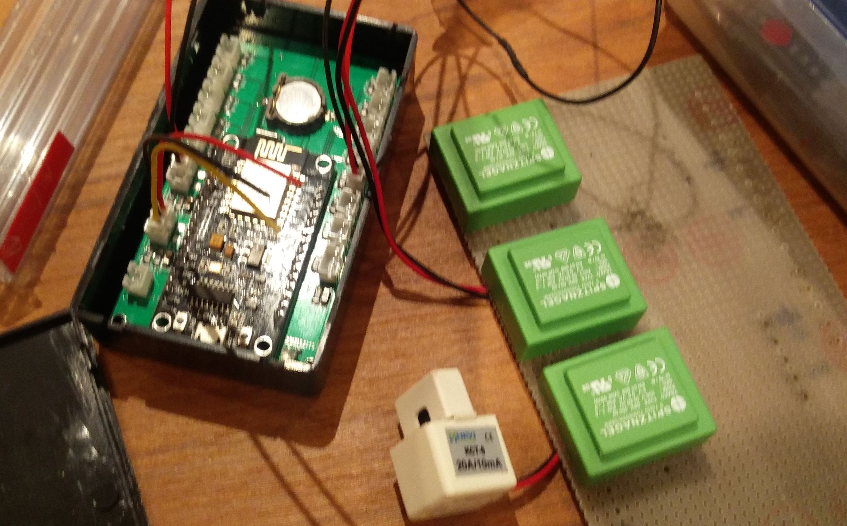
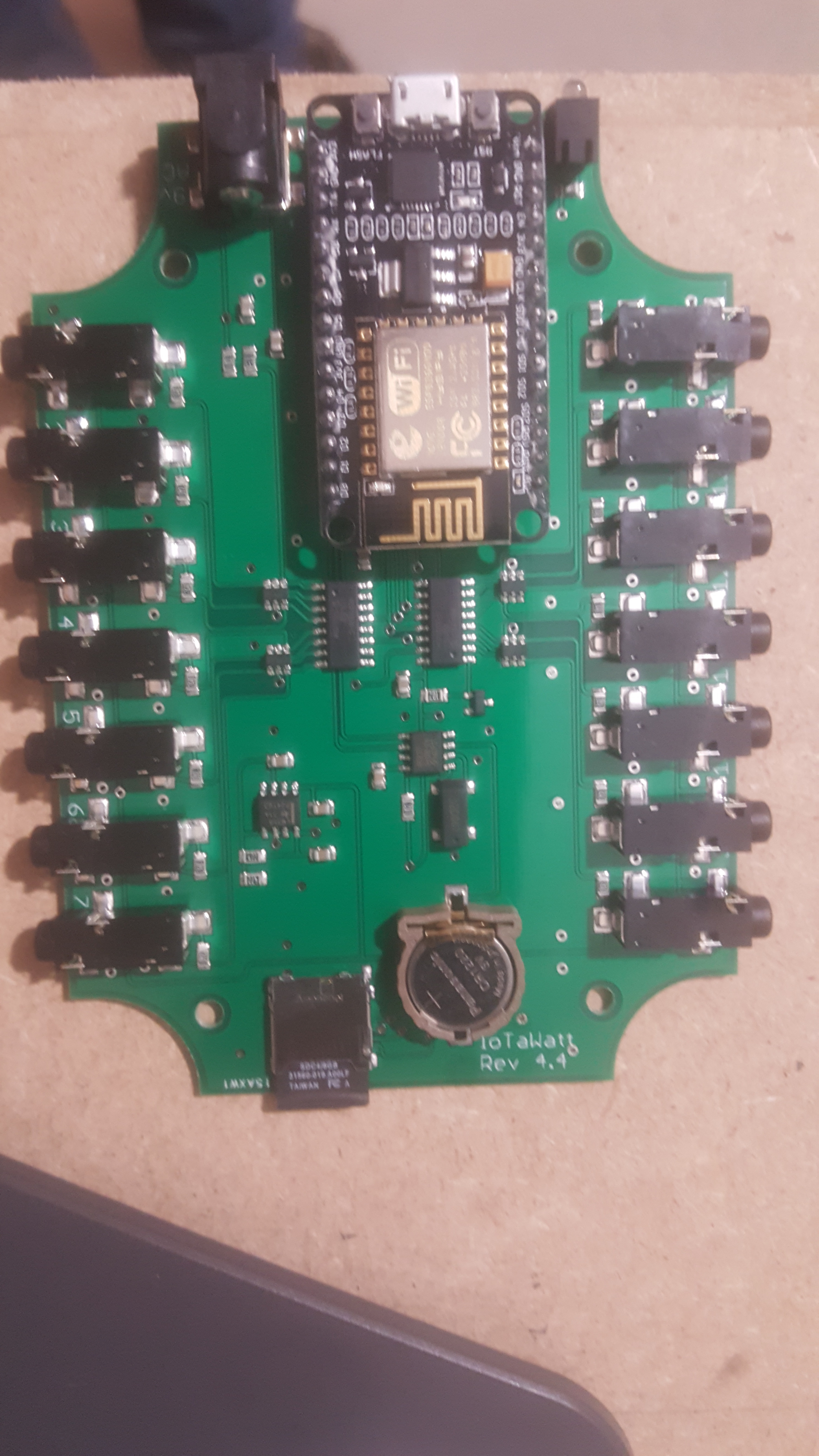
Me and a friend of mine made new pcb designs to accommodate for 3 phase direct measurement all on board (you only have to populate different parts on the PCB). Still in the testing phase but so far everything seems to work. We also changed connectors (cost far less) If anyone is interested i can mail the schematics and PCB design. I even have some prints available (at a price) because my Chinese friends only produce them 10 at a time. I can post some pictures if wanted
Hi everyone! I’m looking to monitor 3 phase power in the U.S. For now I am looking to monitor amperage from each main on a 3 phase sub panel. I would like to find an adapter for direct reference. If anyone can advise me as to where I could purchase one, I would be grateful for that. I am possibly interested your solution too @Nico. I would prefer not to have to make one myself because my soldering skills aren’t that great. Thanks!
Just FYI, if you what you want to measure is RMS Amps, there is no advantage in using direct reference. RMS Amps does not depend on a voltage/phase reference. In fact, you could setup the IoTaWatt as a single-phase system and the Amps for the three phases would still be correct.
A voltage&phase reference is only needed for real-power and metrics derived from that. Even then, I would encourage you to try derived-reference before getting into the expense and complexity of direct reference. You can always change over later if the results are not satisfactory.
Thank you, that’s very helpful. Right now we have a situation where we are sharing power with a neighboring building, so we want to use an IotaWatt to monitor their power usage to help us balance our loads on the three phases.
Eventually we would like to monitor the power at the main panel but the wire is parallel 500 mcm so it is really thick with the 2 wires on each main, 3" I think. Could you recommend a solution for what clamps we could use to accomplish this? We would be doing this for the same reason, balancing loads on the 3 phases. Would RMS amperage be good enough for this or would real-power be desired in this scenario? Forgive me for my knowledge of electrical current is limited, but I am always happy to learn more… thanks for your help!
Edit: Also the service at the main panel is 480volt, 2 of the mains are 120volt and 1 is 277volt or something like that… so this had me wondering if finding reference VTs for the main might be problematic too…
Edit2: Another of our objectives is to balance our loads and maximize our usage on each of the phases. So we would want to use the IoTaWatt to determine the amperage on each phase to make sure we’re not exceeding safe levels of current at any time of the day. Our main equipment is HVAC, dehumidification and lighting
Hello,
I would like to buy two adapter (red pcb) for 3-Phase Direct Reference.
Is it still available ?
If not could you give the electric wiring and the component needed to make it.
Thank you
Thierry
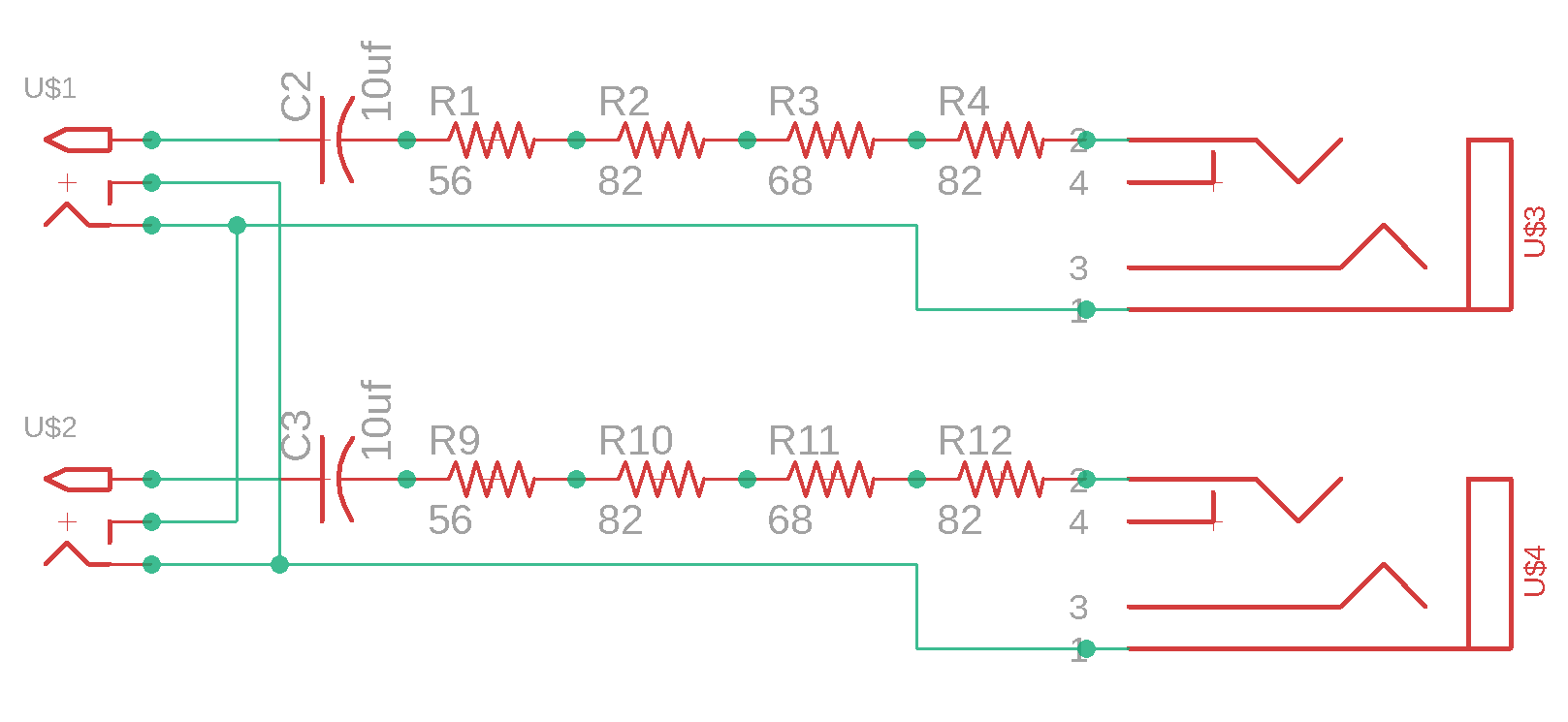
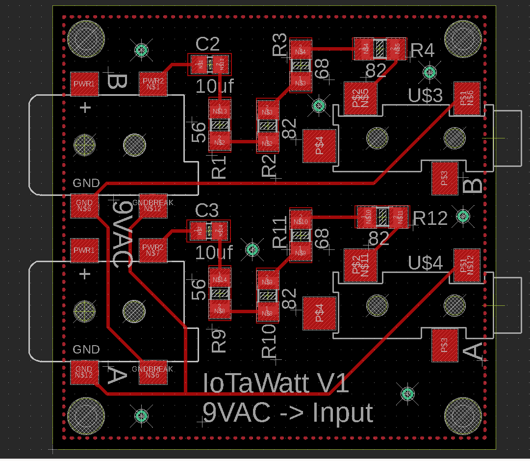
I will try to upload the files on the forum so that others can benefit also. Just remove the .txt extension and you can open them in EAGLE. IotaWatt2.sch.txt (129.5 KB) IotaWatt2.pcb.txt (210.5 KB)
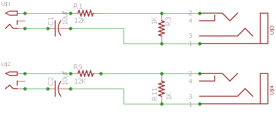
The center pin from the AC-AC 9VAC power supply must pass throw 10uf Capacitor and throw 288 Ohm Resistor.
Questions : Is it possible to have one PCB for each AC-AC 9VAC power supply ?
In other words, does the outer ring from each AC-AC 9VAC power supply need to be connected to the other ?
Let me check what’s on github and correct if necessary.
Not sure what the question is, but with the V2 adapter, you need one board (2 phases) for each IoTaWatt. You can use two AC adapters to feed any number of boards by using commodity splitters usually sold in places that sell CCTV equipment. They are very inexpensive and come in x2 x3 x4 x6. You can also split a single AC adapter for the primary AC inputs to the IoTaWatt as long as you maintain the same polarity.
With the V2 adapters, you also need to remove the burden resistors inside the IoTaWatt for the inputs that will be used for AC reference.
That’s an old unit, I’m surprised that you have not used it yet.
Most of the three-phase users are using the “derived three-phase” method that only need one AC adapter. I would recommend that you try that out and see if you get satisfactory results before attempting to make AC adapters and removing the burden resistors. The method is described in the WiKi and requires no additional equipment.
Thank you for your answer.
I also really need to monitor and compare each phase voltage…
What about the further stock expected 26th Oct 2018, still need removing the burden resistors to monitor the 2 other phases ?
If yes, in the event I buy two more IoTaWatt (one for each phase) do you think it will possible to pick up the data from each IoTaWatt and synchronize those data into one IoTaWatt database or in a outside database (Synology NAS…) ?
Is there a big difference between my old unit and the coming new units, in terms of measurement precision ?
Best regards
Thierry