CT Sensor Amps Question(s)

Looking at picking up one of these units in the next few weeks and I did have a quick question on the various CT amp values, etc.

Question: Should I purchase CT modules that are close to or just above the circuit’s rated amps or stick with the three that are recommended (019, 013, 006) because of calibration purposes even if the circuit is a 30A or 50A; where a 100A CT would be placed?

I would suspect the following:
2 x 200A for the US mains (could I not use 100A on each as commercial one do?)
6 x 100A for Solar (40A), Garage sub (50A), Barn sub (100A), Dryer (30A), A/C (30A), Range (50A)
6 x 20A for Furnace (20A), Freezer (20A), Well (20A) Washer (20A), DishW (20A), Fridge (20A)

Or, would I want to get CTs that more closely match the various 100A, 50A, 30A, 20A circuits in the panel?

1 Like

There is a lot of discussion on this topic at the OEM site, and their recommendations are typically to try to match the CT as closely as possible, and then to adjust the burden to get full range. I assume that is good advice for their equipment, but IoTaWatt seems to do fine over a wide range without much consideration for the range beyond insuring that it can handle the maximum expected. In all fairness to the OEM equipment, most of the advice is developed for European 230V systems where the current is half what we see in the US for the same power.

You will get excellent results using a 100A SCT013 CT on a 20A US branch circuit. That said, I use and sell Echun CTs that are better matched for the current ranges for several reasons:

They are UL recognized and comply with the IoTaWatt UL tests.
They have longer, better insulated cords.
They are typically smaller for their rated current.

I can supply the following:

ECS24-200 200A ,24mm opening, $22.89
ECS16-100 100A, 16mm opening, $12.69 (functionally the same as an SCT013-000)
ECS10-50 50A, 10mm opening, $9.40
ECOL09 50A, 9mm opening, solid core, $6.55

I also have some ECS25200-C2 which are easy clamp on type CTs for mains - $25.41.

I will have a store open soon to sell the IoTaWatt and these CTs. In the meantime, I have been doing some sales by Private Message (PM) and paypal.

Whatever you decide. If you go with the OEM shop, that’s fine, but I would recommend against using STC006 20A CTs.

@Overeasy,

Thank for the quick and detailed reply to my post.

I would be more than happy to discuss picking up the ESC models with you over PM if you would like.

I assume the IoTaWatt supports these models you are selling and unsure of any calibration using either if put on a smaller circuit load, or if one is listed as a supported device in the configuration making it plug and go?

For the US mains as it is 200A total over the two circuits, does one only need to have 100A CTs for each side and not 200A, or could one side carry 200A if there was some issue with the wiring?

Also, I guess having a CT that is rated above the circuit level is ok, so for my 30A circuits using a 100A CT is not a problem, but the reverse would be; correct?

While US 200A service is indeed rated for 200A on each leg, you would have to have a lot of things on all at the same time to come close to that. If you have two 5 ton air conditioners, the electric dryer, the electric oven, and two electric water heaters all on at the same time you will be getting close.

Under more normal conditions it is hard to get to even 100A. But, 50A sustained is not too unusual for a largely electric house.

I have 100A CTs on my main lines and have never come close to saturation with them.

Thanks @frogmore for the input. I have seen many of he commercial units (Curb, Sense) use 100A on each of the mains, but it seems like to be safe or if you want to future the install, you should go with 200A on each. Not a big price difference for piece of mind… I guess?

Right, plug-n-chug. Here’s a list of the devices supported by direct menu pick:


Beyond that, you can specify the “turns” ratio and phase-lead of any other generic CT.
Same for a number of VTs.

This gets into some gray areas. Most modern US services are 200A, which use two 200A breakers, one for each side of the split phase. In theory, the box will handle 200A on each side. 240V loads add to the total of both sides. 120V loads only add to the total for the side they are on.

Some older US homes have 100A panels. It’s the same as above only the limit is 100 per side.

All that said, Bill Thompson on the OEM forum has a good explanation of the practical limits of residential services based on the capacity of the utility transformers used to supply them. In addition, there are box loading formulas in the code that electricians use to prevent running the panels near or at capacity.

The SCT019 CTs are rated at 200A. They have a ratio of 6000:1 which means they would be at full scale at 250A when used with an IoTaWatt. That’s what I have had in my main panel for more than a year and my accuracy is better than .5% when compared to the meter.

The ECS24-200 (and ECS25200-C2) are 4000:1 ratio. They are full scale in IoTaWatt at 167A. By all accounts that’s more than enough and in the unlikely event the current were to exceed that, the grace leeway would get you to 175, and the protection diodes on the input would prevent any damage after that.

Here’s are my two mains in early April with the heatpump running on a cold day. I prrposely drilled down to 10s intervals so that IoTaWatt’s averaging would not hide the peaks:

There’s a lot you can do with the graph visualization tool once you get some representative historical data.

It’s a trade-off. You get better resolution and perhaps accuracy with the smaller ones. If the current is higher than the CT is designed to handle the core will saturate. This is generally not harmful for a short period of time.

Note that the transformer supplying your house probably can’t deliver 200A for any length of time. Most houses share a 25KW transformer with a few others. 25KW is about 100A. My house has it’s own 25KW transformer, but that is fairly unusual in higher density areas. My old house shared a 25KW transformer with 3 or 4 others.

Going with a 200A transformer instead of a 100A one means you lose a bit (literally) of resolution. That is not that big a deal, until you are trying to measure differences of less than 10-20W or so.

But, do what feels right to you.

@overeasy,

Once again thank you for the detail and extra input. I really like the clamps on the ECS25200-C2 you have listed and think I will go that route for the two mains when there are a few IoTaWatt units also in stock in the near future. I like when something is set to Plug and Chug! :slight_smile: I also like how you can break out the mains and it is quite revealing how they are used when you have visibility into them with the product. What we miss when we just do not know. I’m almost scare to install one of these as it will show just how spoiled we are.

We will be having solar installed in the next month or two, and I do not think what the circuit will be install for that (research says about 40A for 7.1kw system). I also understand how important it is for the direction of the CTs as the solar will be a supply and the grid will be consumption. I would like to get the product in and running prior to solar to see the difference. I’m a numbers guy and love the charts and graphs. Too awesome.

Sounds like you have some great knowledge of the bigger systems out there. We have 200A to the house and I believe a pole transformer feeing our house and two others. We are also on what I believe is a 1350 line (?) so it is a major feed to the rest of our smaller town.

So, you would recommend 100A on the two mains, and the same for anything 30A or above in the panel? I know on Aliexpress, YHDC sells various rated models such as 20A (not recommended by anyone), 30A, 50A, 75A, 100A and 200A. Sounds like @overeasy recommends going with the models he have available for obvious quality concerns. And for the smaller stuff, just get a few 20As and done.

Thanks for taking the time and your feedback.

By way of example, here are six CTs
ECS1050 - 50A max
SCT013-000 - 100A max
SCT019-000 - 250A max
ECS24200 - 150A max
ECS25200-C2 - 150A max
ECS16-100 - 100A max

There is no special calibration. Just plugged them in a few minutes ago.
image
They are all around a single conductor hooked up to a light bulb array with one each 100W, 75W, 60W. Stepping through the combinations:

imageimageimageimageimageimage

So even at very low current of 0.5A - 2A, the “mains” type CTs are just as accurate and have equal resolution to the 50A “branch” type CT. The SCT019 quickly goes to about -1% from the others, but that is calibration, not resolution. The QC is maybe not as good on those as the Echun, plus they are 6000:1 vs 4000:1, 2000:1, 1000:1. But in any event, excellent results could be obtained using any of these, even on 20A branch circuits.

The accuracy is due to the IoTaWatt having a precision 0.2% voltage reference onboard, as well as sampling at nearly 10 times the rate of some older technologies with 12 bit ADCs. That was the design goal: Get away from the nitty-gritty of custom firmware, burden resistors, and calibration factors.

2 Likes

@overeasy, wow that is amazing and so cool. Just to bounce it off you, below is an image of what I would be looking at for a set of CTs. I was not really sure of the difference of the two lower (solid core or Not), but I would think for 20A circuits one could use the non-solid and for the 30A-50A use the solid. Hope this is the correct thinking. Always looking for good, but if I can save on some of the smaller circuits it may not matter going cheaper.

Thoughts on the below?

First, for the obvious reasons, I must recommend that you have a qualified electrician install these, especially the solid core that require actually disconnecting and reconnecting high voltage circuits. At the same time, I can only go by the typical usage of these appliances. An electrician would be able to examine the nameplate rating and insure proper capacity. In particular the sub-panels, the A/C is impossible to guess at, and the an electric furnace would certainly exceed the 20A capacity so I’m assuming it’s gas or oil and the primary load is the blower.
Mains are fine.

Barn Subpanel:
Typically, a sub-panel is 240V, so you would either need two ECS-100, or you would have to clamp it around both the red and black conductors in opposite directions. Sounds complicated but actually pretty easy. When you say barn I have to wonder if it’s high current, because if the total of both sides can exceed 100, you would be advised to use an ECS24200.

Garage sub-panel: Same logic as the barn.

Solar: ECS10-50 should be fine for 7.5kW.

Range: Electric ranges require the same treatment as sub-panels because they typically use both 120V and 240V.

No issues having an electrician do the work, yet I have also bee in my panel quite a bit (mains off) and previously ran some of my own circuits. Each of the devices I have listed are the actual circuit breaker rating on the listed items. Would you recommend using something that does not requite the removal of the wires. I was not sure if the main differences between the two models apart from solid core and not.

The Garage sub panel is a 50A where the previous owner did some auto repair work and had an electric heater; now removed. The only thing fed from the panel today apart from outlets are two garage doors (1/2 HP) and a mini-split A/C for the lower part of the house. This is a single run like a range, so it sounds like for anything that is 240v I would need to either double the connectors or join them as you suggest to have a single sensor pickup for both.

The Barn sub panel was a new install when we had our barn remodeled and they pulled 100A circuit for lighting, some networking gear and security cameras (POE), yet in the winter we do have to run two heated water buckets which I think will pull some extra Amps (but I’m sure a 50A would have supplied our needs. 100A may be just a safer option for a new install. I agree, I will need to add a 100A for the other side of the barn to make things easier.

You are correct on the “furnace” as it really is an oil burner for both the boiler and one for the Hot Water. So the current is only needed to get it started things started. I will have to go back and though through the 240V is this could impact the number of devices or CTs now. Thanks for checking.

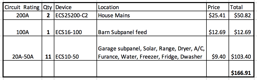
Looks like the following would be 240V in my configuration: Range, Clothes Dryer, Barn, and Garage. I may do the turn around option for these so I can have more sensors then less. Nothing else I can think of is 240V. Is a typical Solar install 240v I would have to assume?

Lastly (I think), I assume you can combine two lower amp circuits that are really the same device such as the A/C unit which has a 15A for the blower in the Attic and a 30A for the outside condenser. If I put a single CT around them, we could be able to bind the used current for the one device, correct?

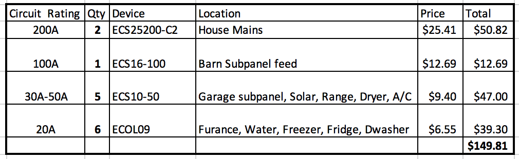
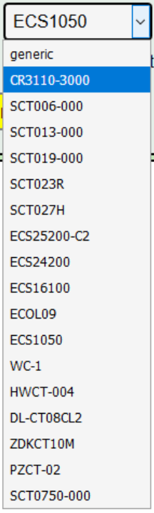
Looking more like this may be a better option and give me flexibility:

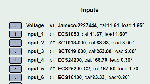
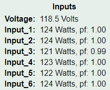
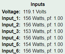
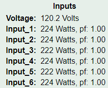
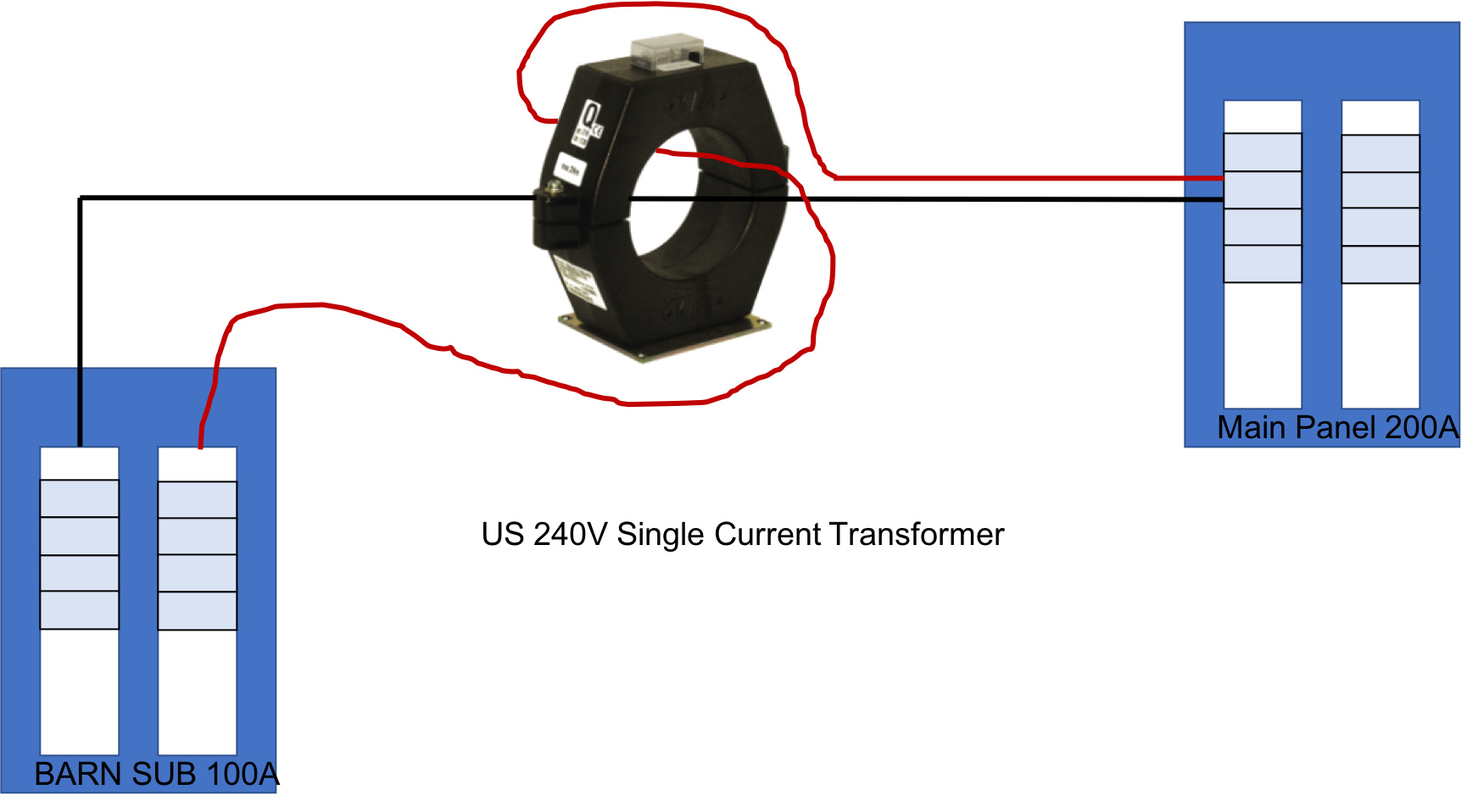
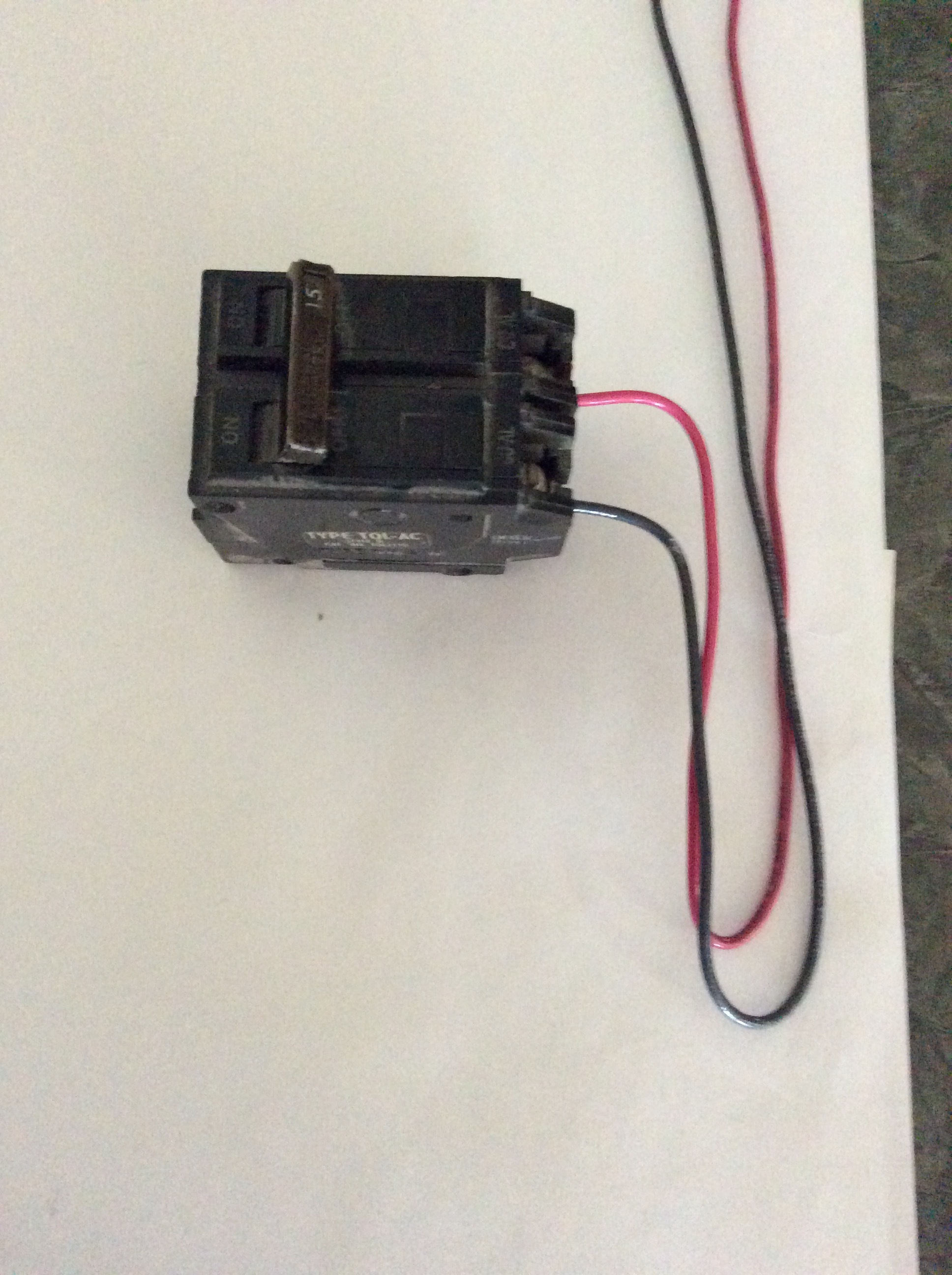
Here are a few images for my panel at 240V items and an image/question on twisting one leg of the cable around in the CT.

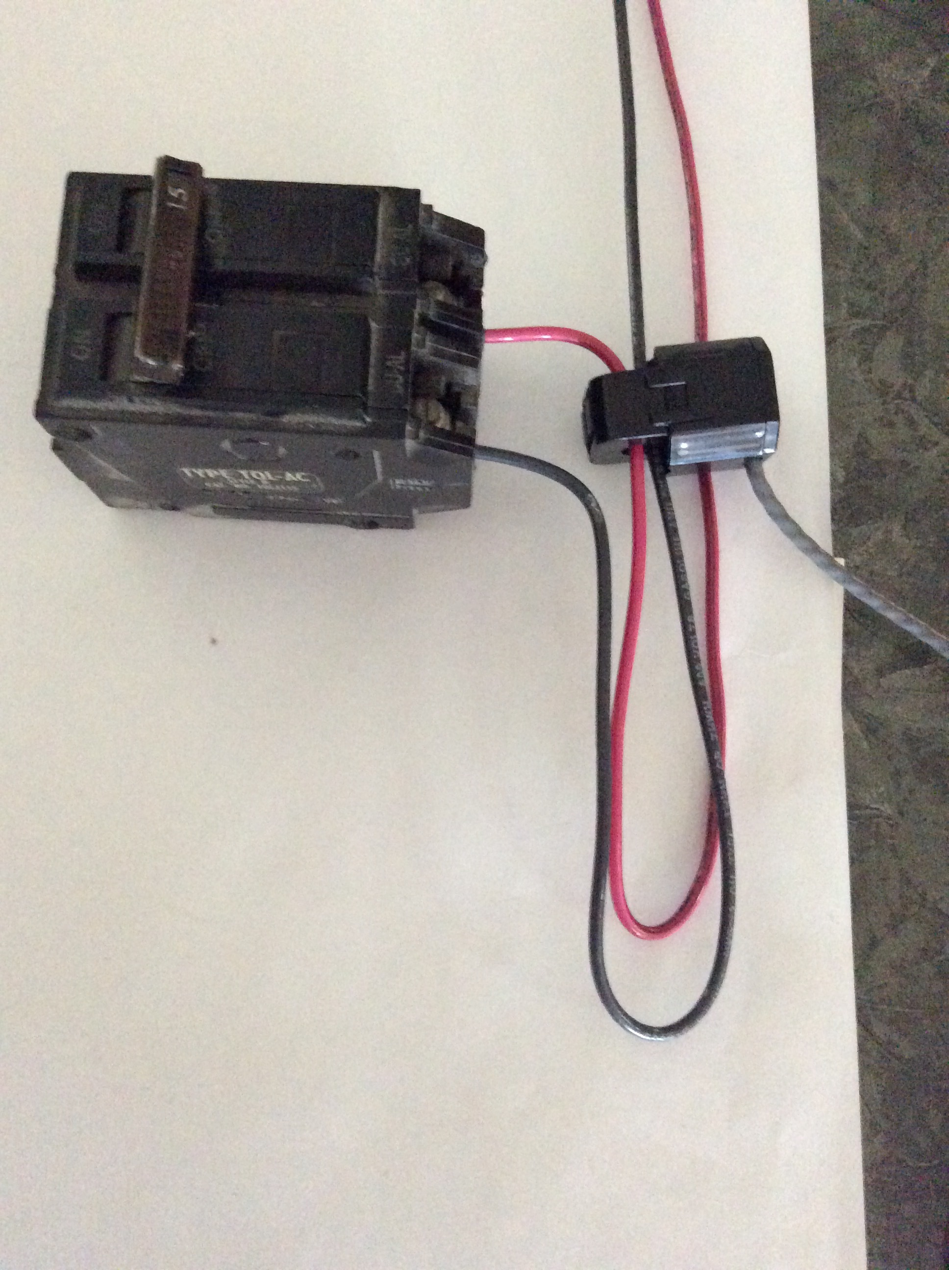
When you say turn around one of the wires in a 240v circuit (sub panels, dryer, AC) do you mean like the below? Do you not get both negative and positive values in the configuration? Maybe I’m missing something as I thought they were directional sensors and such a configuration would show positive current for one flow and negative current on the other leg.

Is the reason you cannot do the below is that you only get 1/2 the current measured do to the 120v reference current?
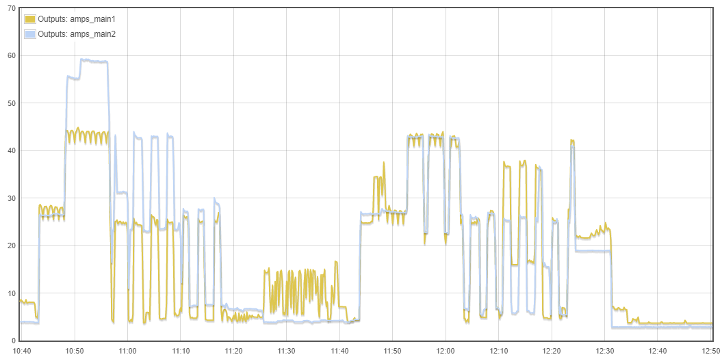
I also saw this article from the learn section of OpenEnergyMonitoring.org, but it is not as clear on the aspects of monitoring a US 240V circuit using a single CT. Use in North America — OpenEnergyMonitor 0.0.1 documentation

Anyone else have anything they can find on this?

I know this is hard to understand. Consider this: when you install CTs on single 120V breakers, they should be oriented in one direction for circuits on one leg of the split phase, and the other direction for circuits on the other leg. This is because there is only one voltage reference transformer and the voltage on the two legs is exactly opposite. So when you reverse the CTs on the other leg, you reverse the current signal as well and it now matches the voltage reference from the other leg.

So when you run the conductor for one leg backwards through the CT for 240 volts, it’s like reversing the CT on that leg. If you did not reverse one of the conductors, one would yield positive current and the other negative, cancelling each other out. What you would be left with is any difference in current between the two. In the case of a balanced load, that would be zero. In the case of a branch panel with various 120V circuits, it would be the amount of unbalance between the two legs.

There are other ways to handle the branch panel. You can put an individual CT on each leg, reversing one, and combine them with a headphone splitter before inserting into the IoTaWatt input. That would be the same as using the single CT with a reversed conductor, except that now, the CTs only need to be rated for the maximum capacity of the one conductor rather than the total combined load.

Thanks again @overeasy for the feedback and details. I assume that one needs to do this turn for any 240v circuits or only for the subs? Something like the well, dryer, etc would also have a single CT but one phase reversed, correct?

I’m not sure my panel will be able to add more CTs (it is older and cramped already). So I would rather get some close info than do the double CTs. If you go the way of the splitter, do you get the same resolution or lose anything?

Just let me (Us) know when they are ready as I’ m ready fro you to take my money for CTs and the IoTaWatt device (power plug, etc.). :slight_smile:

For dryer, well pump, probably A/C, you only need to put a CT on one leg and then double the value using the output “calculator”. I am also adding the ability to specify that the basic input should be doubled in an upcoming release.

In a past life, when I was wiring a 240V panel, I ran allof the conductors to the bottom of the panel and then turned them up to the appropriate circuit breaker.


In this way, there is flexibility to move circuit breakers around within the panel. This is common practice among many electricians. I bring it up because it really facilitates connecting a CT to a 240V circuit with one conductor reversed:

The CT is an ECS10-50 and fits pretty well into the space.

I can confirm that most of the wiring in the panel does have a decent loop and pushed to the one side, so like you have shown, it looks like for the sub-panes (barn/garage) I will have one CT and reverse one of the legs as shown above. For the other 240v services such as the dryer, pump, etc. I just put it around the one and double the reference voltage in the UI.

Sound just too easy, again, take my money. I’m sold. Not just on the product, but the great service and consulting services as well!

For a dryer and stove, you either should put both conductors through one CT or use two CTs. Dryer motors are typically 120V, so you would either not count it or double count it with only one CT and one wire. Stoves vary in terms of how they use power, but can and do only use 120V some of the time. Pumps and water heaters generally don’t get wired to the neutral, so a single wire, single CT works fine for them.