Have someone tried 'Talema AZ Series' CTs?

Hi,

I’ve been using IotaWatt for a month and I’m very happy with it :smile: I started using a couple of SCT-006-000 and SCT-013-000 in a temporary setup just to play around with it.

I was searching for solid core CTs and I came across to these: Talema AZ Series
Have someone tried this type of CTs?

They are available at Mouser/Digikey/RS for a reasonably low price (~3-5€ each), so I bought one of each type (AZ-0500, AZ-0750, AZ-1000) to measure the energy generated by my photovoltaic inverter and compare them with the other CTs that I have.

Right now I’ve configured in IotaWatt three generic input channels selecting the proper number of turns (500, 750, 1000), but I left “Phase lead” parameter to 0.00, how can easily I determine the correct phase shift values for these CTs?

To answer your question:

  1. You can send me a couple and I’ll test them.
  2. You can measure the shift with your IoTaWatt vs. your VT.

For option 2:

Install the CT on a conductor that will carry at least several amps. Loop the conductor through multiple times to multiply it if necessary.

Apply a purely resistive load. Incandescent light bulbs are good. Toasters are good.

Use the browser command: http://iotawatt.local/command?vtphase=INPUT where INPUT is the input channel of your CT.

If you get a large number, reverse the CT or the VT and do it again. I would guess that a CT like that will be less than 1. Add the result algebraically to the configured VT shift to get a reasonable shift value for the CT.

Shift varies with current, so there is no perfect answer, but with solid core CTs it’s usually low and behaves well at the low end. Nevertheless, try to do it at the typical current the CT will be asked to measure.

Couple of other things:

Those CTs don’t appear to have TVS diodes, so be careful not to energize the primary without shorting or connecting to the IoTaWatt.

Thanks for the detailed response @overeasy :blush:

From what I’ve read in this forum, you should live in the US, I live in Italy and a shipment of a small packet would cost way more than the actual values of these CTs. I’d prefer to fund you directly in order to buy those CTs even others to improve the overall IotaWatt product.

That’s a really nice feature, I’ll do some test in the weekend and than post here the results.
Right now I’ve collected some data of the production of my photovoltaic inverted, it generates with a power factor of almost always 1.0, yesterday the energy measured by CT that I’m using was

  • SCT-006-000: 10.661 kWh
  • SCT-013-000: 10.710 kWh
  • AZ-0500: 10.466 kWh
  • AZ-0750: 10.552 kWh
  • AZ-1000: 10.512 kWh

These results are with phase shift configured to 0 for Talema’s CTs.

That’s correct, no TVS diodes built in. Thanks for reminding me about that.

That’s probably close to what it is. Solid core CTs can be .1 to .3. The small variation really doesn’t matter when you are dealing with unity PF (1.0). It only matters with highly reactive loads.

Those results are pretty consistent. 3 significant digits is about as accurate as you should expect (<1%). In several installations I get the same result with HWCT-004 solid core CTs on Solar Inverters. The kWh are consistently within 1% of the energy reported by the (solar edge) inverters.

I would put these CTs in the same category as HWCT004 and DL-CT08CL02. I do think the echun ECOL09 is slightly better, has TVS diodes, can do 50Amps, and comes with a long cord and 3.5mm jack.

Hi Bob,

I also have a question about this: if I do this for an ECS24200, I get the following numbers:

Channel: 12
Refchan: 0
Measured shift: 25.31 degrees
Artificial shift: 28.12 degrees (60) samples
Net shift: -2.81 degrees

Is net shift the size I’m looking for? As voltage reference I use an Ideal 77DE-06-09(EU) with a phase lead of 1.78. If I add the two numbers I get about -1?

I know that the phase lead for the ECS24200 is already available, but I’m trying to find the right number for an ECS24400.

The shift in the tables for the VT was done at 240V 60HZ. That was before I had a 50HZ capability. Also, the shift for the ECS24200 is at 60HZ. So I’ll get you better numbers at 50HZ. The ECS2420p is very low shift anyway, so I don’t think you are that far off, but right, I don’t think it lags.

I can’t do this until middle of next week, but before then, can you tell me what the current was when you tested this? The phase shift of the CT will vary with that.

1 Like

Thank you Bob, that would be great!
The current was 12.45 A (fan heater and toaster together).

If it is not too difficult, the factors for SCT0013, SCT006, SCT0019 and Ideal 77DE-06-09(EU) at 50 Hertz would also be very interesting.

The SCT006 is a waste of time because phase shift is all over the place. I have also now realized that I don’t have a 77DE-06-09 Euro AC adapter. I have the D8-06-09 UK adapter. I will test that but it may be quite different from the EU adapter. I have SCT013 and SCT019.

1 Like

If I understood correctly the phase lead has to be adapted by measuring a known pure resistive load (PF 1.00) and adapt the phase lead to obtain the PF = 1.00 ?

Not sure exactly the context of this question so I can’t answer yes or no. The phase adjustments for CTs are measured with a pure resistive load, but this thread deals with alternative field methods. My test apparatus measures the CT against the direct line phase (no VT). The phase adjustments for VTs detailed here is also a provisional field technique. My tests again use the direct line phase to establish the shift. There is no “load”, unity or otherwise, involved.

The net result of the phase adjustment mechanism is to have a way to compensate for shift given any combination of VT and CT. This is an approach that I believe is unique, and to be sure, controversial with some folks. Nevertheless, I have confidence that it contributes well to the overall accuracy that IoTaWatt seems to be able to produce in a wide variety of applications.

1 Like

I ordered via alibaba CTs (they claim they are class 0.2s) now I would like to see what are all parameters I have to set for the CT.

I ordered 2 kinds
A) 16A/50mA, there I have to set 16/.0.05= 320 turns
B) 40A/50mA., there I have to set 40/0.05= 800 turns

Now the question what do I have to set for the phase lead ? For the moment I placed +2.00

The answer is at the beginning of this thread:

There are the results:


Phase Lead Shift: 00.00
Sample phase lead

Channel: 14
Refchan: 0
Measured shift: 151.94 degrees
Artificial shift: 28.12 degrees (60) samples
Net shift: 123.81 degrees

854 Watts, pf: 0.99


Phase Lead Shift: 00.00
Reverse: checked
Sample phase lead

Channel: 14
Refchan: 0
Measured shift: 27.91 degrees
Artificial shift: 28.12 degrees (60) samples
Net shift: -0.22 degrees

Shows reverse symbol and 853 Watts, pf: 1.00


Phase Lead Shift: 02.00
Sample phase lead

Channel: 14
Refchan: 0
Measured shift: 151.94 degrees
Artificial shift: 28.09 degrees (60) samples
Net shift: 123.85 degrees

853 Watts, pf: 1.00


Phase Lead Shift: 02.00
Reverse: checked

Sample phase lead

Channel: 14
Refchan: 0
Measured shift: 27.94 degrees
Artificial shift: 28.12 degrees (60) samples
Net shift: -0.19 degrees

Shows reverse symbol and 853 Watts, pf: 1.00

What Shall I change?

Note to anyone reading this thread and thinking - Whoa! this is way too complicated. Most of the commonly available CTs have been measured and all you need to do to use them is select the model from a configuration dropdown list. This thread deals with how to use a CT that is not in the tables. I am disappointed that after spending considerable money, time, and effort to collect multiple samples of the common CTs, not a single user has come forward with option A to send me samples of other CTs and contribute to the overall success of this project. I get a lot of “Gee thanks for all the work you’ve done”, but not much what can I do to contribute?


This data indicates that this CT has nearly the same phase shift as your VT, whatever that is. The net shift measured is about -0.20° (lag). So you would add that value to the phase correction of your VT (shown in the configure inputs display) to arrive at a reasonable field value for this new CT. If you have an Ideal 77DE-06-09(EU) for instance, the phase adjustment for that is +1.78° (leads) -0.2° = +1.58°. Call it +1.6°.

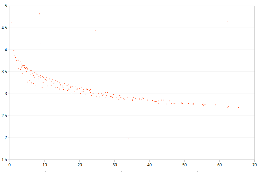
CAVEAT: This is a provisional field measurement. There are a lot of variables involved with phase correction, most notably the fact that phase shift is a function of primary current, and it’s particularly volatile at low primary current. Here’s that function for the ubiquitous SCT013-000.


You will notice that in the tables IoTaWatt uses a phase correction of 3°. That’s pretty accurate at 20-30A primary current, as might be expected on a European main.

Phase shift is also pretty significantly affected by line frequency. It is greater at 50Hz than at 60Hz. although it affects both the VT and CT similarly, so the net is usually not that much different when using 60Hz phase adjustments in a 50Hz environment.

Burden value also affects shift. So if you are using that SCT013-000 to measure a low current circuit and decide to increase the burden to get better range, you increase the phase shift. Better to use a lower turns (and shift) CT in the first place.

Finally, these measurements are only valid with pure sine-wave signals. I take pains to insure a good quality AC signal and a pure resistive load when I measure these adjustments. I also don’t use a VT and the algorithms for sampling are tuned to remove sampling shift and there is no capacitive shift in the reference signal.

So these numbers are fine for your own use in the field, but I would caution anyone else to do their own, and encourage folks to send me samples of CTs that are not in the tables so that I can add these devices to the tables with controlled measurements.

I sent a package with CT’s nine days ago, hope it gets there soon :slight_smile:

My apologies Elias. I forgot that you were sending some CTs along with the VT.

1 Like

The problem is that I made a mistake to order only one spare of each type ;-(
and secondly I saw that it would cost around 55$ to ship it…

Thanks for the value, I applied the suggested phase adjustment to +1.58.
The official counter display has a resolution of 1 kWh I have to wait for a bigger ammount in order to reduce the impact of the potential difference.
I have been lucky I just saw the kWh changing on the official meter therefore I can reduce to a maximum diffference to +1kWh.

Therefore 109 kWh from official counter meter and 109.79 from iotawatt → iotawatt shows +0.72%.
In case the previous value of official meter was just before to increase the value I should reduce its value of 1kWh resulting to +1.66%.

As reference with the SCT013 I had -3.78% (calculated on 1652kWh)

Are you still interested in testing other CTs?
I can send you one or two to test. I bought a bunch from Brueltech. They are the micro 40. They are very small and seem accurate enough, but are probably not quite as good as the solid core 50A ones in your store.

I think what you are doing is great and would like to help. What else do you need help with?

You can PM me with your address for shipping the CT(s).

I should say I bought these years ago, before even the esp8266 was a gleam in its inventors’ eyes, let alone iotawatt.