How many outputs can be defined?

Hi:

I guess it depends on the complexity of the expressions entered in the calculator, but I would like to know if there’s any reasonable limit for the number of outputs that can be defined. This what I have now. This is the mains breaker box. I still would like to add total amps and watts, which is the sum of the 3 circuits, so it would include the expression:

(AiresFAh x 8.245) + (AiresFBh x 7.78) + (AiresFCh x 8.94) + (CFEFAh x 2.0253) + (CFEFBh x 1.7127) + (CFEFCh x 1.7022) + ModFA + ModFB + ModFC

Maybe it’s better to simply add wCFE, wAires and wMod at the Grafana query.

Additional question:

A phase of one of the circuits is missing the PF status at the inputs (although it is being shown as an output). Any ideas?

The constant factors are used because we’re measuring circuits that have several conductors per phase (in parallel) and we’re measuring only one conductor of each phase. BTW, we’re now using the 3-phase voltage sensing in direct mode.

Thanks!!!

There is no limit imposed, but you’re right, resources are not limitless. Without getting into the nitty-gritty of what constrains outputs, I’d say it looks safe for you to add some more outputs. The scripts that are stored in memory are actually very small. The use of a lot of constants burns it faster, but you have a lot of heap left. Where you will probably start to see trouble first is maybe you won’t be able to update the config because the json file will be huge (it probably already is). A few months ago I recoded that with a divide and conquer approach that seems to be working. Let me know if it breaks. Most of those outputs are trivial.

Yea, I don’t put out pf under 60 Watts. The CTs are not accurate down there and the ADCs are barely registering. It’s folly to pretend to have an accurate PF. In the 230V world, the cutoff should probably be 120 Watts.

I’ll be interested in any observations you have about that vs derived. I see that your voltages are pretty close, which is encouraging. If you want to try something out, you can do both at the same time and compare the readings of the direct and derived real-time.

Edit: One interesting thing is that I see the AC cycle sample rate is a little low at 32.9. That could just be the status refresh with all those outputs, or a big influx upload, but keep an eye on it. 33 is fine, that’s all 50Hz users get anyway, and that’s at least 2 per second, but I’m interested in the impact that direct reference has on that. It changes the timing of the sampling because it has to sync into a different voltage each sample, which could take more or less time. With a single voltage reference, when I finish sampling a 60Hz cycle, I know I’ve got 8.3 ms until another zero crossing. With direct reference, that’s a moving target. So I’m interested in whether it really sags. If so, it would make sense to group the sampling by phase.

Sure I will. But I’m confident it won’t. It’s working great so far.

Got it. But actually I have a few more questions regarding negative power (See the image below). Note that for this particular breaker box the mains is TPrinC (with the postfixes FA, FB, FC for the phases). Also, ERen is a subcircuit of the mains but connected to a group of solar panels (so that’s why power is negative). This Iota is (so far) connected as “derived reference”.

  • It looks like by not by not displaying pf for power under 60 the pf is also missing for large negative power. Probably there should be some abs(power) < 60 somewhere in the code?
  • Negative watts in the input are very informative. The color is a plus. [The solar panels are btw connected to phases A,B, a 220 V system, but not to phase C, so you see an imbalance.] Question: Have you considered output currents as negative for negative power? That way we could add the currents from every circuit and get the same total current at the main circuit. (The system has a few more circuits, with only the main and the solar panels wired at this point).

Sure. We’ll let you know of any findings. So far our only observation is that when using derived mode is that the single voltage input is named as A. In our facilities, the available power outlets are taken from phase C, so CTs for phases A, B, C at the breakers were referenced to CBA when configured at the inputs.

We may try it once me make more progress with the installation at more breaker boxes.

Interesting. I had not noticed that. One thing tough, I believe the board was not yet uploading to influx. Now it is uploading, but not all the outputs, and the Iota is at 32.1 AC cycles sampled/second. This is the influx config

Actually this other Iota with the solar panels has much fewer outputs and is not uploading (the service is stopped) and the samples are just below 40/s. Is that OK? See the image below.

Statistics

Thanks !!!

1 Like

You got me there. I can fix that. Most folks setup their solar so that it reads positive. But no problem, I’ll make that change.

How does that work? Are you using an inverter for split-phase systems? The phase difference is 120 rather than 180, 208V vs 240V. I see that the power on each leg is not the same, but the current is, so the pf is also different, and it looks like phase B takes the hit, probably the inverter is syncing a split-phase output to phase A. Is there a way to add some capacitors to better balance that phase B?

I have not considered output currents as negative numbers for negative power. The Amps output is RMS amps, which is always positive by definition.

Yea, I was considering using roman numerals to avoid confusion.:smile:

The way it works is that it samples a cycle and then digests the samples. Then it does other stuff as needed (posting to influx, responding to webserver requests, etc. Then it waits for the next zero crossing to sample another full cycle. So the theoretical limit is one sample every three half cycles. In a 60Hz world, the limit is therefore 40 cycles sampled per second (33.3 in a 50Hz world). Three-phase changes that a little, but it should be pretty close.

I love the beating you are giving these things. Carry on.

thanks !!!

I’m not directly responsible for that installation but I can investigate. We also have a power quality analyzer that we’ll soon use for calibration of the whole installation and we’ll find out about the phase angles too. So far what I know is that the inverters are two-phase and that each phase syncs independently to whatever phase they’re connected to (A-B, A-C, C-A, etc) so it makes sense they’re split-phase, but my experience is more related to electronics than to power systems so I can’t really tell right now. Capacitors may be added but I suspect there may be bigger issues there. For starters, I’m now wondering if the neutral wire is correctly specified, considering the load imbalance.

Can you possibly reconsider? Please? After all, in AC systems negative energy can only come from a current flowing in the opposite direction (as actually detected by the CTs). Then again, square roots have always two roots, one positive, one negative :slight_smile:

Now that I see, I made it worse trying to explain my point, haha. Sorry about that.

We will. :slight_smile:

Hi, Bob:

Resurrecting a thread again since it is about the same subject. However, this time is about defining and uploading measurements to influx rather than defining the Outputs.

What I’m trying to do is to upload “everything” to influx then generate CSV files with the measurements from influx (maybe you recall I’m trying to process all data of the last 9 months).

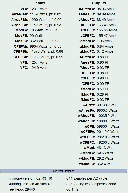
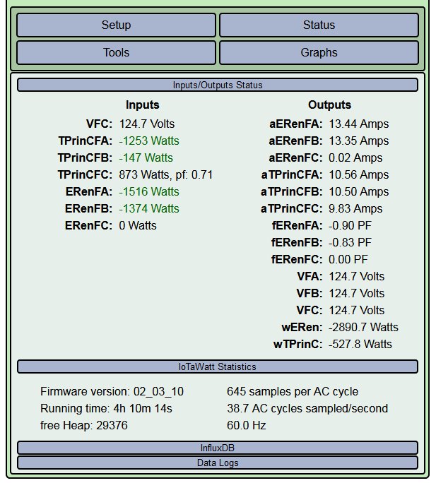
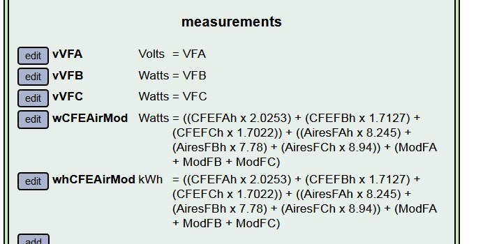
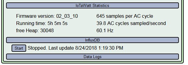
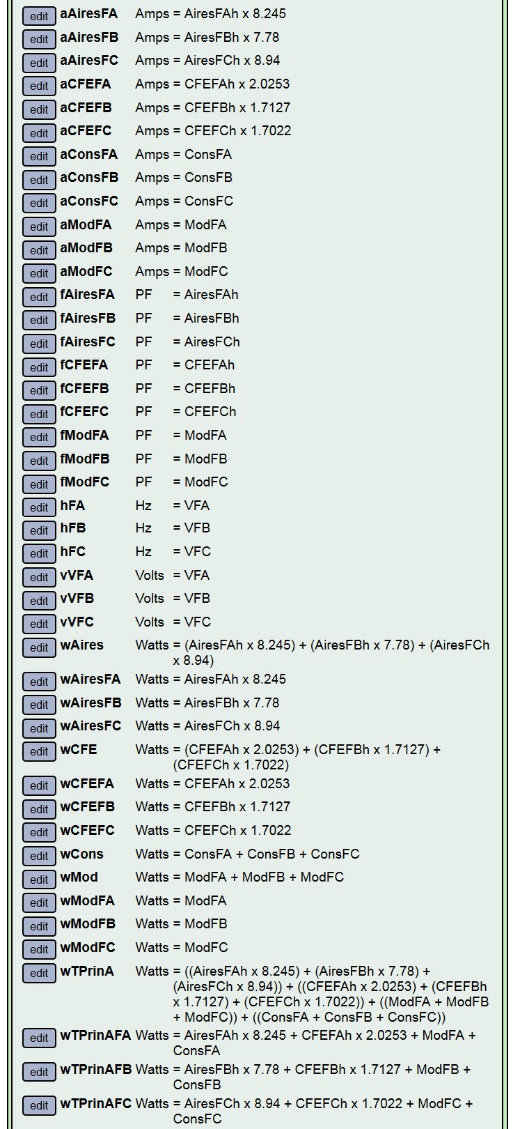
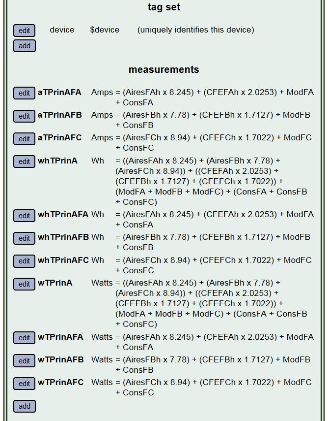
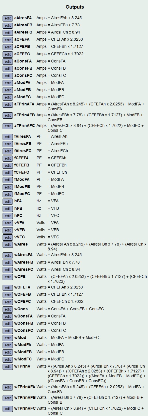
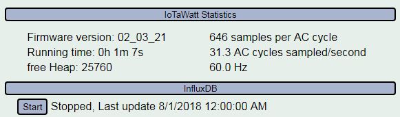
The following is what I would like as measurements (is there a limit? Maybe I should have asked that first), and upload them to Influx every 5 or 10 seconds. Note that the second image, with the IotaWatt Statistics is with the influx server stopped.

IotaWattStatistics

If you consider this is simply too much to ask to the processor I may reduce the number of measurements and compute secondary values in the spreadsheet (maybe getting the Amps from watts and voltage, for example?). I may also try to reduce the number of defined Outputs and/or not view the Status page to reduce the processing load.

Another unrelated issue. The linux box we were using for influx crashed recently and we’re setting up another one. Well, I only tried to stop the Influx server now (for obtaining the statistics screenshot above) and apparently it crashed. I was using Firefox and couldn’t stop it from there, so I opened another window in Chrome and tried to stop it from there but apparently it caused the crash (Note that I didn’t close the Firefox window first and also may have clicked Stop more than once). Well, the server stopped at the end. Here’s the log for this:

** Restart **

SD initialized.
6/13/19 00:59:43z Real Time Clock is running. Unix time 1560387583
6/13/19 00:59:43z Reset reason: Exception
6/13/19 00:59:43z Trace: 1:3, 1:4, 1:3, 1:4, 1:3, 1:4, 1:3, 1:4, 1:3, 1:4, 1:3, 1:4, 1:1[11], 1:2[12], 9:0[12], 9:0, 9:1, 8:4, 8:6, 8:8, 8:9, 9:3, 9:5, 9:9, 1:2, 1:3, 1:4, 1:5[7], 7:0, 15:0, 15:1, 7:4
6/13/19 00:59:43z ESP8266 ChipID: 6910711
6/13/19 00:59:43z IoTaWatt revision 4.8, firmware version 02_03_21
6/13/19 00:59:43z SPIFFS mounted.
6/12/19 18:59:44 Local time zone: -6:00
6/12/19 18:59:44 device name: Iota1
6/12/19 18:59:45 MDNS responder started for hostname Iota1
6/12/19 18:59:45 LLMNR responder started for hostname Iota1
6/12/19 18:59:45 HTTP server started
6/12/19 18:59:45 WiFi connected. SSID=IoTaNetwork, IP=10.0.0.221, channel=9, RSSI -56db
6/12/19 18:59:45 timeSync: service started.
6/12/19 18:59:45 statService: started.
6/12/19 18:59:45 Updater: service started. Auto-update class is NONE
6/12/19 18:59:45 dataLog: service started.
6/12/19 18:59:46 dataLog: Last log entry 06/12/19 18:59:40
6/12/19 18:59:47 historyLog: service started.
6/12/19 18:59:47 historyLog: Last log entry 06/12/19 18:59:00
6/12/19 18:59:50 influxDB: started, url=10.0.3.226:8086, db=example, interval=30
6/12/19 19:00:11 influxDB: Stopped. Last post 07/31/18 23:00:00

Thanks !!!

Carlos

Yeah Carlos, you’re in uncharted waters there. Anything goes.

The line protocol for influx is very verbose. Each of those outputs will probably add 40-50 characters to the frame, so each five seconds is probably close to 2K. So that’s roughly 34Mb for a day’s worth of measurements. IoTaWatt can handle the calculations, that’s trivial. It’s the HTTP load and buffering that dims the lights. Someday I’ll write a codex to compress the highly redundant line protocol, but that’s a serious project.

Big surprise, this exception was in the influx handler. It was in the middle of a series of queries to determine the last post time. I can see a hole that could cause this if starting and stopping. It’s not a huge deal because the restart takes a few seconds and off you go. Trying to synchronize this with the 40 or so queries that this output list produces isn’t practical. Just take the hit and restart.

This is going to take a long time. If you haven’t finished in a month or two, I may have made progress on a query interface. In the meantime, give serious consideration to uploading a larger time interval. One minute will fetch from the history file where the access is a bit faster.

Thanks.

That’s what I thought. No problem.

WOW. It is indeed.

Just for the record. I have not defined those measurements I listed yet. When I was stopping the server it had only three measurements defined.

I’m trying to make the analysis and report with the information we have so far from mid September to now and update it when we have the a full year of data. It will be interesting and fun.

As for the uploading of data, since I’ll be using the historical records anyway I’m now planning on uploading the measurements by groups; maybe 10 measurements at a time. What you think ?

I was going to suggest that. You can use a unique tag to identify each group so that the history will upload even though other group(s) are more or less current.

Wouldn’t the new measurements automatically start uploading from the date in "upload history from " regardless of the tags, just by defining and saving them?

Another question. In influxDB — IoTaWatt 02_03_20 documentation it says:

“with a device name of IotaHome and the current value of the input solar of 2944.6, the following different measurements could be generated:”

How can you decide what format to generate and upload?

Sorry, I’m the electrical engineer (and lead) in this project and I’m not familiar with influx (but I will), although I’ve been playing with some Grafana dashboard components.

C[quote=“CL23, post:10, topic:311”]
Wouldn’t the new measurements automatically start uploading from the date in "upload history from " regardless of the tags, just by defining and saving them?
[/quote]

Yes, you’re right. It will start from the most recent of the measurements defined.

Depends on how you want to report the data. I use the defaults.

OK.

I figured out the format now. Thanks. I’ll send you a message for some very specific details.

We tried uploading one measurement then adding a second one and it didn’t work: The second measurement started uploading at the date/time where the first one was at that moment and not from the “upload history from:” date. That, or Influx dropped the older measurements.

The tags were the same on both measurments. So I guess using your initial advice of adding different tags for each group is a must. We’ll try that tomorrow.

Thanks.

1 Like

You have to remove the measurements that have already uploaded. It begins after the most recent of all the measurements specified.

You mean remove them from the Influx config at the IotaWatt or from the Influx DB ? Sorry, maybe a dumb question.

From the influx config in the IoTaWatt.

With a very simple test, it worked. We tried on a Iota which is being used for some tests and has a minimal configuration, although all inputs are used.

Now I’m trying to upload to Influx from the IotaWatt with the historical data and have defined the first 11 measurements. There are 50 defined outputs too.
Before I start the server I was trying to check some graphs and the Feeds don’t show. Could this be memory related? I could reduce the number of outputs but I wanted to check with you. I’m in Firefox usually but also tried with Chrome and still doesn’t work.

thanks.

Feeds%20not%20listed

Can you enter the following URL into your browser and post the results:

iotawatt.local/feed/list.json

Substitute your IoTaWatt device name or IP address if not iotawatt.

Thanks for replying quickly.

I forgot to say: All the outputs were already defined before the measurements were added. Three measurements were defined from our previous tests, but I deleted them before adding the 11 measurements shown.

When requesting the json file the contents starts displaying then aborts with the following message:

SyntaxError: JSON.parse: unterminated string at line 1 column 3120 of the JSON data

I used a plugin to capture the RAW data:

list.json.txt (3.0 KB)

I tried using the File Manager of the IotaWatt but I guess that file can’t be downloaded from there. If you need me to copy it from the microSD memory just let me know.

Thanks!

Apparently the payload of the Json response was truncated. This goes to the original title of the thread. As more and more outputs are defined, the limits of various resources are tested. The IoTaWatt has pretty limited RAM and there is no virtual memory.

From what I can see here, the problem could be in one of two subsystems, neither of which I have control over. I could make this work but that would only set it up for the next capacity issue. There comes a point where I have to just say can’t do it. This is that point.

The problem is in sending all of the inputs and outputs to the browser. I’m curious to know if the graph ever worked with all of these outputs defined. If so, then lets have a look at the message log to see if it is taking an exception and restarting when this happens. That’s what I would expect if the heap were exhausted.

I doubt this has any direct bearing on the measurements configured to influx. They take a little heap, but nothing significant in this context.