IotaWatt Voltage and Phase Reference AUS

All (or Bob :wink:
I am currently using the OpenenergyMonitor 9VAC for voltage reference, with a UK-AUS adapter plug, the
IDEAL 77DB-06-09

I have procured from Jaycar 9VAC 1A Unregulated Power Supply 7DC Plugs | Jaycar Electronics,
a Powertech MP3027 9VAC - 1000mA, 9VAC AC-AC adaptor.

Is this OK ?, Its 1000mA, as opposed to the 667mA of the IDEAL 77DB-06-09

thanks

Should work ok. You would configure it as a generic and should get some reference to calibrate.

For best results, you would need to determine the phase shift. There are a couple of ways to go about that. The easiest would be if you are a three phase user and have one of the VT adapters to add extra vts.

Please advise if that’s the case so I can offer the most appropriate me5hod for the equipment that you have.

I am single phase, but have a true RMS AC voltmeter Digitech QM-1321, which i used to calibrate my iotawatt which is currently using the 77DB-06-09 with a UK-AUS plug adapter.
I just want to eliminate the plug adapter is all.

Sure, you can use that and calibrate, but you will need to specify a phase shift for the transformer. There are ways to measure it with the IoTaWatt, or you can just try something like 3, which is a typical number for a 1amp VT.

I am using a M9233 • 9V AC 1.33A Appliance Plugpack from Altronic here in Australia which is similiar power pack

Thanks rosspeel
How did u go about calibrating the phase ?

ended up being VT, generic240V, cal:21.68, lead:2.00°

Rosspeel
Thats cool with the configuration, thanks for that,
But for my education (learning heaps here), how did you validate that those settings are correct,
with single phase

thanks

I’m working toward using read-the-docs to build a new documentation resource to replace the wiki, which is harder to manage. There are a lot of undocumented features that I will address then.

The IoTaWatt has the ability to measure the phase angle between any two input signals. When those signals are nearly pure sine waves, as the VT is and a CT signal from a purely resistive load (unity PF), it is a measurement of the phase shift. I calibrate the tables using a direct line voltage signal adapter, but users can measure the relative shift between a somewhat calibrated signal and an unknown signal to get a reasonable relative calibration. I plan to document that when I get some time. Three phase is not really a factor in all this, it’s just that provides the ability to compare to another VT as opposed to isolating a CT with unity load.

I checked what my display on my inverter where outputting and in real time set the voltage on the IoTaWatt interface and watched as both changed over a short period of time to sync them as close as possible.

overeasy
thanks heaps, looking forward to the doco
I calibrated the VT against a True RMS voltmeter, but i assume that this is not phase calibration ?

It’s not. Could you post a screenshot of the input configuration display? I’d like to verify that you have a viable guesstimate configured.

overeasy - here is the VT calibration - thats just for voltage, cant find phase ?iotawatt-vt-calibration

overeasy - heres the inputs

If you select a generic vt not a generic240 vt you can input the phase. Use the same calibration factor.

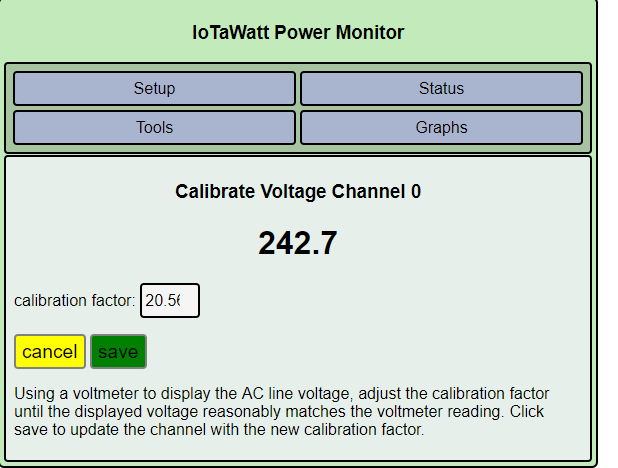
The phase correction is indicated by the " phase lead 2.00º ". That’s a phase correction of +2.00º. That’s a pretty good estimate and probably will give you satisfactory results.

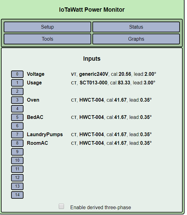
I see that you are using some HWCT-004 CTs. Those are solid core CTs with very low phase shift of +0.35º. You may be able to use the CT on input 3 to directly calibrate your VT if it is truly just a resistance oven (not a microwave or convection).

To do so.

  • Turn on the oven and see if the PF reading is 1.00. You might see .99 if the VT is really not close to 2.0º.

  • Use the browser url: iotawatt.local/command?vtphase=3 to obtain a measure of the relative phase difference between CT3 and VT0. You should get a low negative number. Do this several times to insure there are no sampling errors.

  • Subtract the resulting phase difference from the phase correction of the CT (+0.35) to get the phase shift of the VT.

So for instance if the measurement was -1.82º, the math would be 0.35 - (-1.82) = 2.17º.

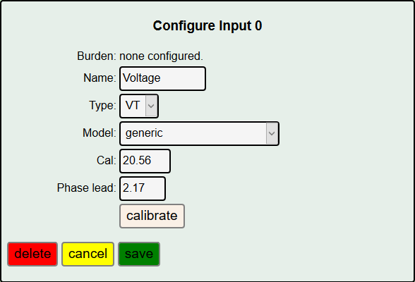
As advised by @Giraffe above, change the VT to the simple generic where you can enter the phase shift and specify your already determined calibration of 20.56, along with a phase of 2.17:
image

This would be a good exercise on your system because the phase corrections used by IoTaWatt were determined at 60Hz, and they are different at 50Hz. For most users with CTs in the 2º-3º range, with a VT in the same general range, the difference is pretty much a wash, but when you use the lower shift solid core CTs, the relative differences are greater, so calibrating phase is a good idea for your setup.

Taking you through it on a bench system here:

image

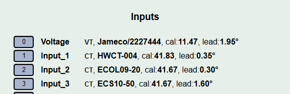
I’m going to use input 2, a solid core ECOL09-20 because the HWCT is backwards and that’s a little more complicated. I’m using some light bulbs for a resistive load:

image

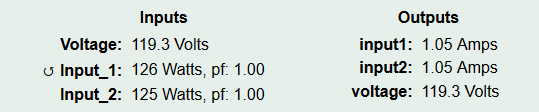
Now I run the phase measurement command and get:

Sample phase lead

Channel: 2
Refchan: 0
Measured shift: 31.88 degrees
Artificial shift: 33.59 degrees (60) samples
Net shift: -1.71 degrees

So if I subtract that from the ECL09-20 configured shift of 0.30 - (-1.71) = 2.01º.

That pretty close to the 1.95º that was the independently measured phase lead of my VT (measured against an unshifted AC line input). Note that when IoTaWatt does the vtphase measurement, there are no corrections applied. It is the raw phase difference between the two input signals. There is also a 0.06º sampling shift that IoTaWatt corrects for all measurements. That probably is the cause of the slight variation in our results.

So there you have it. Field phase calibration.

1 Like

overeasy

thanks heaps for the detailed explanation - my oven is an electric oven that i can run in “no fan mode”

great reply and very detailed, Iotawatt is in good hands no doubt