Sorting out an Australian three-phase installation

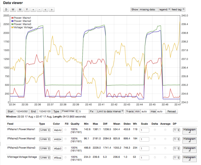
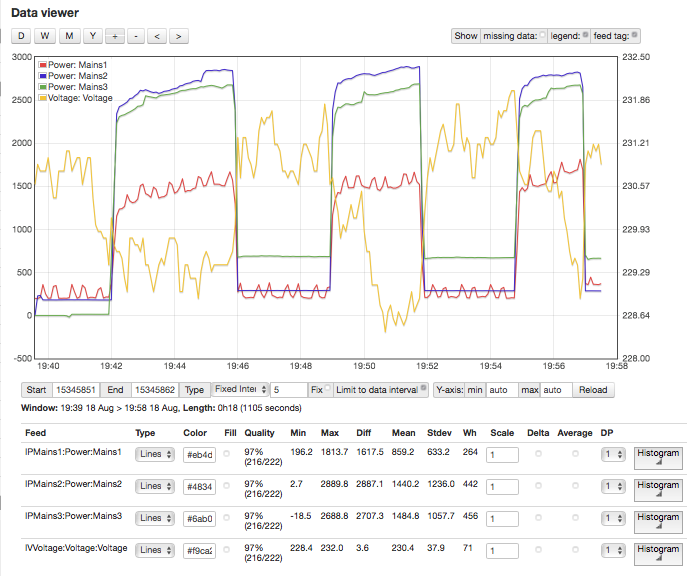
Thats a much better and more reliable way to do it.
Ideally I would leave it another 24 hours (as we moved CT for Mains 3 yesterday) and it might be good to give it some additional time.

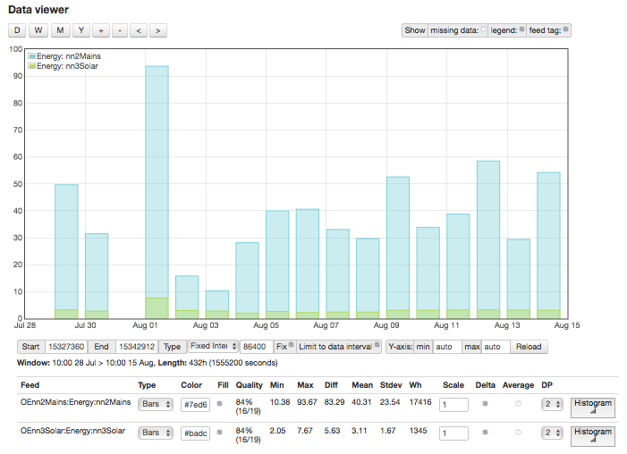
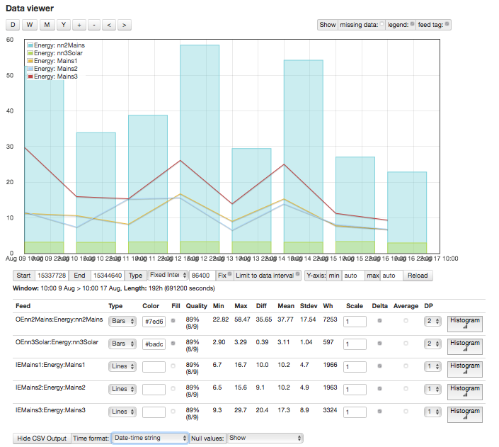
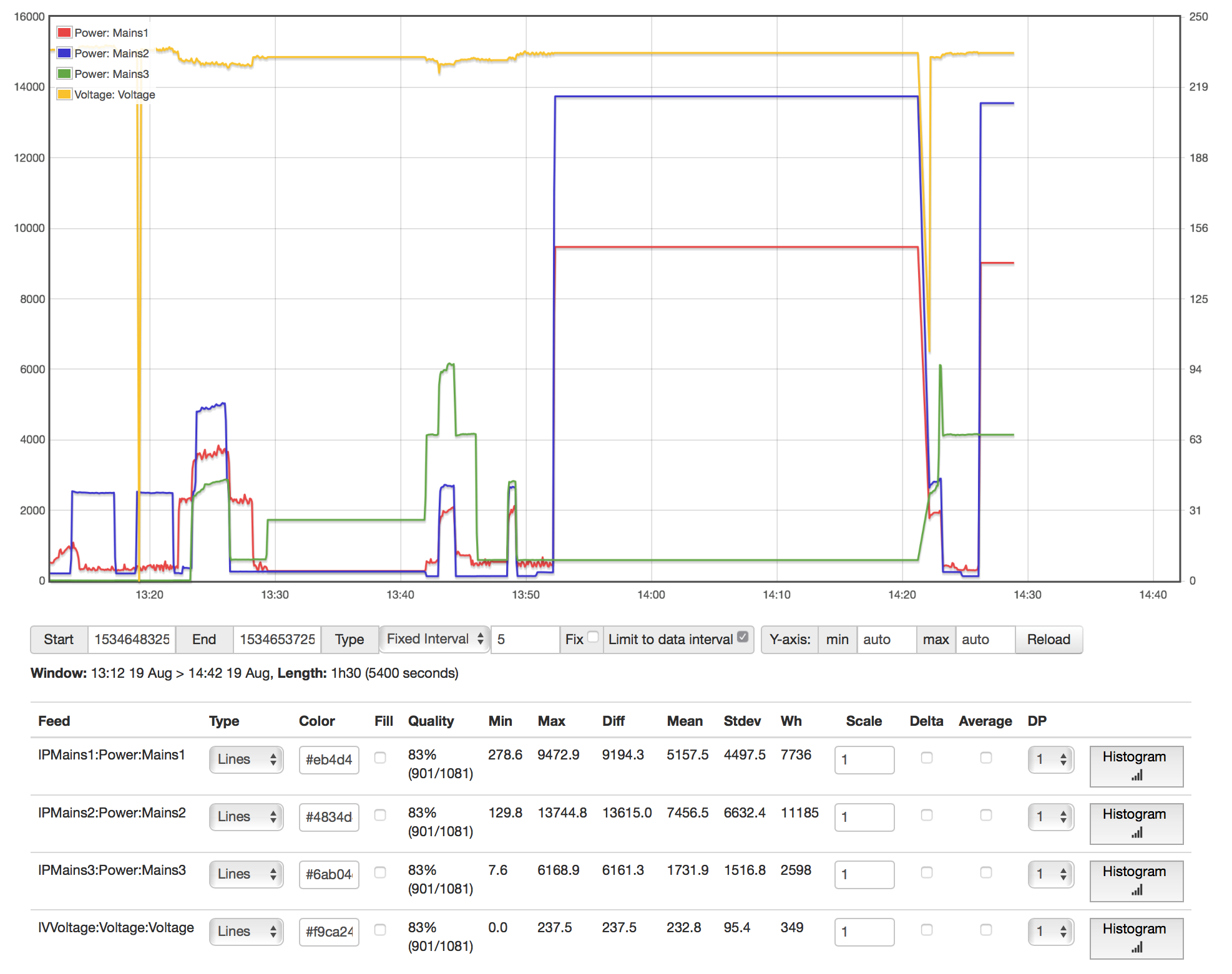
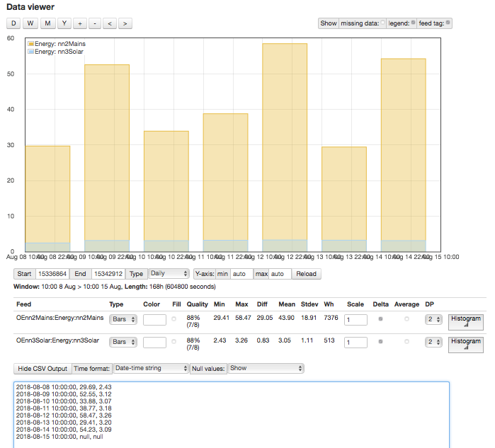
Graph is below. I have left the csv in there so you can see both the Mains and Solar totals.

Actual reads from the meter will go here shortly:
As mentioned, the solar is pretty much accurate.

Date Mains Meter
07/08/2018 27,737 53
08/08/2018 27,790 25
09/08/2018 27,815 54
10/08/2018 27,869 44
11/08/2018 27,913 46
12/08/2018 27,959 76
13/08/2018 28,035 44
14/08/2018 28,079 69

So at present it seem to be under-reading but it might be that with the change to Mains3/C we are now ok. Lets give it another 24 hours.

Here are the readings updated for today. Keep in mind that its really only the last 3 that we think we have configuration correct (so last 2 readings as we are trailing by a day).

We are now much closer but only reading 80% of actual.

I will get out the multimeter and take a quick look at voltages for A/B/C and post readings.

Date	Mains	Meter	IotaWatt
07/08/2018	27,737	53	33.08
08/08/2018	27,790	25	29.69
09/08/2018	27,815	54	52.55
10/08/2018	27,869	44	33.88
11/08/2018	27,913	46	38.77
12/08/2018	27,959	76	58.47
13/08/2018	28,035	44	29.41
14/08/2018	28,079	69	54.23
15/08/2018	28,148	35	27.02
16/08/2018	28,183	0

Added the graph for completeness.

@overeasy Please let me know if you want/need any of the serial capture log files. I have continued logging for now but would like to clean that up eventually…

There’s still something wrong. Could you do that plot with the three individual mains instead of the total and show the CSV?

I thought this might be a good start.

Will plot a second one with Mains/Solar Removed. I can turn off the delta if you want overall totals rather than daily.

2018-08-09 10:00:00, 52.55, 3.12, 11.2, 11.6, 29.7
2018-08-10 10:00:00, 33.88, 3.07, 10.6, 7.4, 15.9
2018-08-11 10:00:00, 38.77, 3.18, 8.2, 15.3, 15.3
2018-08-12 10:00:00, 58.47, 3.26, 16.7, 15.6, 26.1
2018-08-13 10:00:00, 29.41, 3.20, 9.0, 6.5, 13.9
2018-08-14 10:00:00, 54.23, 3.09, 15.3, 13.9, 25.0
2018-08-15 10:00:00, 27.02, 3.29, 7.7, 8.1, 11.2
2018-08-16 10:00:00, 22.82, 2.90, 6.7, 6.8, 9.3
2018-08-17 10:00:00, null, null, null, null, null

NOTES:
I will update both sets of graphs after 10:00am
I will include the CSV from the graph
I will also add the Meter Stats
According to my timestamp you were happier with the install (change and reverse CT for Mains3) from 15th August, so we maybe have 3 decent days.

Updated reads and graphs as of 10:00 so they should line up with prior readings.

As per previous I would only be going from around the 14th onwards and would take earlier with a pinch of salt due to CT on Mains3

Meter Actuals vs Iotawatt

Date	Mains	Meter	IotaWatt
07/08/2018	27,737	53	33.08
08/08/2018	27,790	25	29.69
09/08/2018	27,815	54	52.55
10/08/2018	27,869	44	33.88
11/08/2018	27,913	46	38.77
12/08/2018	27,959	76	58.47
13/08/2018	28,035	44	29.41
14/08/2018	28,079	69	54.23
15/08/2018	28,148	35	27.02
16/08/2018	28,183	34	25.10
17/08/2018	28,217	50	37.66
18/08/2018	28,267	0	

Graph:

Graph CSV Output

2018-08-11 10:00:00, 38.77, 3.18, 8.17, 15.28, 15.32
2018-08-12 10:00:00, 58.47, 3.26, 16.72, 15.63, 26.12
2018-08-13 10:00:00, 29.41, 3.20, 8.99, 6.53, 13.89
2018-08-14 10:00:00, 54.23, 3.09, 15.30, 13.91, 25.02
2018-08-15 10:00:00, 27.02, 3.29, 7.70, 8.11, 11.22
2018-08-16 10:00:00, 25.10, 3.31, 7.34, 7.01, 10.76
2018-08-17 10:00:00, 37.66, 3.15, 9.99, 8.08, 19.59
2018-08-18 10:00:00, null, null, null, null, null

Please let me know if you want a seperate graph of Mains1/2/3 with no delta or anything else…

EDIT: update graph & numbers with extra day

So right, last three days, IoTaWatt total power has been ~80% of meter power.

To recap where we are:

Given the spaghetti wiring, it has been difficult to determine the phase/load relationship and we’ve been concentrating on trying to get the mains correct. We determined with resonable certainty that the VT was connected to Main1 here. So Main1 is phase A.

We determined that the hot water heater was connected to Main3 here.

We determined that Mains3 is phase B using unity power factor of hot water here. So by elimination Main2 is phase C. This is somewhat supported by the order in which the Mains are presented to the meter here. Note that the sequence right to left on the back of the meter is B, A, C. I don’t know if 3ph meters work like 3ph motors, but if so wiring it A, B, C would have made it turn backwards, so I’m guessing that without color codes, they just connect them up arbitrarily and if it goes backwards, they swap A and B.

So the last piece was to insure that all of the CTs are facing the same way with respect to line/load, and that was corrected. So now I believe that the mains measurements are setup correctly. Yet the readings have been ~20% low for several days.

Going Forward:

Expectation for the mains with derived reference is at least within 5% hopefully better. So I’d like to continue to pursue that 20% difference. My suspicions, in order of interest, are:

  1. One or more CT is reporting low.
  2. There may yet be an error in the configuration/setup.
  3. There are gross voltage deviations between the phases.
  4. The meter is wrong.

So to further explore the obvious #1 there are a few things that can be done.

Take all of the CTs, configure then for phase A. Mark each with a unique number using a felt tip marker, and clamp them on the Main1 line at the same time. Observe the power recorded on each and note any outliers. Do this at both lower and higher power. Also note variations in power factor when above a few hundred watts. Reinstall and configure with the most consistent CTs on the three mains. Wait a couple of 24hr cycles and see if there is better agreement.

If you have a decent true-rms clamp on ammeter like a Fluke, you can configure outputs for each of the mains with Amps as the units, then compare the meter to the IoTaWatt Amps. They should be within 1% on all phases.

My suspicions, in order of interest, are:

One or more CT is reporting low.
There may yet be an error in the configuration/setup.
There are gross voltage deviations between the phases.
The meter is wrong.

I agree 100% with your thoughts and would like to propose the following steps - if you think its ok as its a tweak to your process:

  1. Identify 2 loads (ideally around 100w and 1000W but whatever we can find).
  2. Try and get an independent measurement to validate what they are actually pulling.
  3. Remove all the CTs (video process so I can see exactly where/orientation they were on.)
  4. Loop through the the CTs on the Phase A/Circuit with the load (and just that load)
    a) are they all reading the same measurement (record any deviation and sort/ the CTs)
    b) is that measurement correct to what we know it should be (eg 100W measured vs 100W load)
    c) assuming we have consistent CTs, repeat the process for a circuit on Phase B & C
    e) report back.

I know this is slightly different to running agains MainsA but it means I can control the power draw and there is one less variable.

Other notes:
I have received my next batch of 10 x SCT-013 but I think it will be a week or two before I get the next IotaWatt and 2 x VTs from the UK.
I will source a clamp True RMS meter

If you are ok with this then I will proceed - if not I can measure the other way but figured it was better to at least start with an idea of how accurate our CTs were before we then spent days with each one measuring mains.

CThat’s kind of complicated and introduces some new variables. Your mains cables are real long, so it would be fairly easy to clamp a bunch of CTs to the same cable and see if they are in agreement. I’m looking for outliers more than poor calibration.

I think most, if not all of them, will be accurate. I’m looking for something that is bad. The last two problems resolved this week involved CT issues. One must have been a problem with installation because it resolved. The other was a broken core in a ct causing it to read low. So I’d like to check yours for outliers and go for the hat trick.

OK - lets go with simple first and then add steps as needed.

  1. Remove all the CTs (video process so I can see exactly where/orientation they were on.)
  2. Add as many CTs as practical to Mains A Load
  3. Measure and log them with small and large loads
  4. Report back.

@overeasy I will proceed and do the full test in daylight tomorrow so we know what the CTs look like but…

That said there is a chance for sauna/air con tonight and I have my doubts about CT for Mains1
Why? Was looking for spikes/oddities in the voltage vs Mains ABC and this is recurring theme (see graph below) - Mains 1 is always low… Could be our dud…

Sticking a brand new CT on it for now.

Mains1 reads low vs Mains2 and Mains3. Also voltage shows odd measurement in same period

so…i was wrong…its something else and will do a full CT test as discussed.

This is with 3 x new SCT-013 100A on mains1/2/3 and cranking up the AirCon.
Same weirdness on Mains1

This is consistent with other unexplained issues we’ve encountered. It explains the 1300 watt hair dryer and the lower reading on mains1 during the light bulb test. Also, pretty much aligns with the 20% meter disparency.

At this point it’s necessary to rule out a problem with the IoTaWatt channel 1 being used for that CT. I’ve not had any issues with quality but what we are seeing could be a low burden resistor. So can you swap inputs 1 and 2, swapping the phase assignments at the same time, then crank the AC and see if the low value stays on 1 or moves to 2?

I think we are close to solving this.

UPDATE: This also looks what would happen if Mains1 has the wrong phase assignment. As I recall the assignments were:

Mains1 = phase A
Mains2 = phase C
Mains3 = phase B

Can you verify that’s the current configuration?

Mains1 = phase A
Mains2 = phase C
Mains3 = phase B

Can you verify that’s the current configuration?

This is indeed the current configuration!

I have made the change and inputs are as per below.

I will line up the CTs for some comparison reading testing in a day or so.

51%20pm

Really just need a graph of the three mains through an AC cycle.

Its coming :slight_smile:
Just waiting for the washing machine to finish - 5 mins

Notes:

  • I made the changes requested at 13:20 and you can see the dip.
  • Aircon was turned on at 13:25
  • I did note some weirdness in the Phases and pf numbers and made and deleted a post as it seemed to clear up after a reboot but it doesnt stay clear…
  • I will post another graph in an hour or so with more cycles so we can zoom a little more.

Graph after about 1 hour of AirCon

Graph after a few hours of AirCon
Basically showing the same as before. Strange goings on on Phase1.

Examples of Weirdness re pf
(Have a feeling that we might have to do the CT/IotaWatt test to rule out any component failures then restart)


Example with the AirCon and HotWater going.
Looks better but pf isn’t locked in to 1.00 (which it had been before)

To get some more info I also fired up the Sauna again.

The extra little bursts from Mains3 are the hot water for peoples showers.

We still show a voltage dip every time we get significant use on Mains1

This experiment was just to determine if there was anything unique about channel 1 of the IoTaWatt, to rule out a problem there. Although all of this does open up new questions, I think it does indicate that the IoTaWatt is working fine.

We swapped channel 1 and 2 to see if the low readings on channel 1 with the AC running moved with the CT. It did. If it had been the channel, mains 2 would have gone low and mains1 would have gone higher.

Another clear indication that the channels and the CTs appear to be working properly is the graph with the sauna. That appears to be true three-phase around 12kW, and all three mains appear equal with that running.

Without examining the AC system, I can only speculate. I’m starting to think there are one or more single phase motors in there that cause the imbalance between mains. I’d expect the compressor to be three-phase, but maybe the air handler uses single phase blowers on mains 2 and 3. Regardless, I think the AC imbalance is a red herring with respect to reconciling with the meter.

I see that your system has updated to 02_03_13, and there may be a recurrence of problems with zero voltage. I changed some things because of other unexpected consequences. The voltage dips of 5-10 volts when high loads kick in is probably accurate in my opinion, but that Combined with the large load swings is increasing my suspicion that derived reference may not be appropriate for your setup.

Agreed - the Sauna shows that we get some balance across the 3 phases assigned and they are close. I suspect the AC has multiple single phase units combined - eg compressor/fans/etc Ultimately its not as issue as long as we can get a handle on the total draw.

I see that your system has updated to 02_03_13, and there may be a recurrence of problems with zero voltage

I am guessing this was because I am on ALPHA and did a power cycle to remove the laptop.

We have now changed the 3 x CTs on the mains with new CTs from a new batch.
We are still reading low and I would like to get that addressed somehow.

derived reference may not be appropriate for your setup

Not quite sure what you mean here and very happy to take direction.
I assume this means we need to get 3 x VT across the phases. We will have a second iotawatt soon but not sure how/where to confiture the 3rd VT.

I will do the CT test tomorrow to see if we have any outliers - will also list circuits and suspected phases for going forward.

I think my next steps are:

  1. Do the CT test/audit on Mains1 (PhaseA) circuit with as many CTs as I can practically fit there and then post results. - audit all of them so I know if we get any outliers. (I can also get a TrueRMS clamp if needed to confirm whats really happening.)
  2. Post a table of circuits (planning purposes - eg connecting CTs and VTs in preferred fashion)
    Why (I want to get input as to how you want me to configure them as I we will be using at least 2 and possibly 3 iotawatt units).

Background Stuff
a) There is another IotaWatt coming with 2 x new VT. Will test to see if we get anything different on the Voltage reads (it also means I have 2 of the same units and can compare against my current though I understand it shouldn’t make any difference once calibrated.)

b) Also awaiting instruction/thoughts from @overeasy re derived reference / other approach to monitoring.

Once we have a plan for configuration that seems to work, I will organise an electrician to come in and clean up the installation and run me another external power point setup (so we can nicely mount the VTs/iotawatts/cables/etc)
I was hoping to defer this until I had some readings as I think I want to significantly upgrade my solar but wanted to get some stats first. Should it be needed we can also trace phases.


Table for Planning:

Circuit Phase amps CT IotaWatt-Unit IotaWatt-Input InputName Notes
Mains1 TBC nn Mains1 Mains input/service fused
Mains2 TBC nn Mains2 Mains input/service fused
Mains3 TBC nn Mains3 Mains input/service fused
Solar TBC 20 Solar Volts read high at Solar Inverter (240 vs 230 at box)
HotWater TBC 20 HotWater Single Phase
Aircon1 TBC 32 Aircon1 3 Phase input / single breaker
Aircon2 TBC 32 Aircon2 the aircon doesnt seem evenly balanced across
Aircon3 TBC 32 Aircon3 all the phases
Garage1 TBC 32 Garage1 3 Phase input / single breaker
Garage2 TBC 32 Garage2 Workshop and Sauna
Garage3 TBC 32 Garage3 Sauna
Sunroom TBC 20 Sunroom Sunroom/part of recent renovation
Shed1 TBC 32 Shed1 3 Phase input / single breaker
Shed2 TBC 32 Shed2 Fridge room
Shed3 TBC 32 Shed3 Pool pump/setup (need to check out)
Lights1 TBC 16 Lights1 House lights - these circuits are close together and
Lights2 TBC 16 Lights2 if they are on the same phase we can use a single CT
House1 TBC 20 House1 will map/figure out and give a better name
House2 TBC 20 House2 will map/figure out and give a better name
House3 TBC 20 House3 will map/figure out and give a better name
House4 TBC 20 House4 will map/figure out and give a better name
Oven TBC 20 Oven Basic 20A Single Oven on Circuit