Reversing and Doubling down

Lately, I’ve been working more on helping folks troubleshoot their installations. Most of the problems have to do with proper installation and orientation of the VT and CTs. This is especially true with derived three-phase setups where a reversed CT is hard to detect. Unlike single phase installations, IoTaWatt cannot automatically correct a reversed CT with three-phase. As we’ve worked through problems, step-by-step, there is frequently a need to physically reverse a CT, and that can be difficult to do. So I’ve been fooling around with a software solution.

Another problem that comes up is that since the proper orientation of the CTs is really relative to the orientation of the VT, sometimes it’s better to reverse the VT. With a US plug, and I believe a Euro plug, that’s possible. I believe the UK plug is polarized so not possible there. Even when possible, sometimes it’s not physically possible due to clearance. So a software solution there might be handy as well.

Another issue is using one CT to measure a 240V circuit in a 120/240 split phase environment. The resultant power must be doubled, and IoTaWatt makes that easy in outputs, but the status still shows half power and it’s necessary to multiply it wherever it’s used in an output. Queue up another software solution.

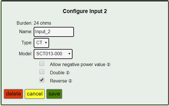
What I’ve done is add a couple of new options to each input configuration. There was already an option to allow negative values. This effectively suppresses the correction of negative power values where reverse power flow is possible, mostly in mains where solar can cause power export. The two new options are “Reverse” and “Double”.

Reverse does the same thing as physically reversing the CT, without getting your hands dirty. It doesn’t really help that much in single-phase environments except that it can remove that annoying ↺. It will also be very useful if one of the mains is backward, as those are tricky to remove/install and they must be reversed if negative values are allowed.

In a three-phase environment, there are dozens of incorect combinations of phase assignment and CT orientation, and working through them can be difficult when it requires reversing CTs. With the reverse option, any setup can be configured, even remotely, without touching the CTs or VT.

You’ve probably already guessed that its available for the VT as well.

Double will make the power output of a 240 volt circuit report correctly by effectively doubling the voltage. There are physical methods doubling 240 volt circuits, like passing both conductors through the CT, and often that’s needed if there is a neutral, but for a water-heater, well-pump or solar inverter, one is usually enough.

Here’s what the input looks like:
image

This will probably go into the next release, and as I work on updating the documentation, it will make things simpler for everyone as there will be a lot less manipulating the VTs and CTs once initially installed.

You can have an electrician do a physical install, even with low-cost solid core CTs, and then configure and orient the CTs as appropriate without the need to go back into the breaker panel to reverse CTs.

3 Likes

That looks like a great idea.

In australia we can’t reverse the VT easily. If an AUS <–> US adapter is used it can be reversed 180 degrees, but if we are using the AUS or UK adapters we are pretty much stuck.

Appreciate you thinking of this and allowing for it in software.

Bob, I just ordered my iotawatt and CTs, will install soon, and this may be cleared once I get the gear. I assume the input setup changes are in the current release, which should mean for a US split phase install, the physical CT and VT direction and phase should not matter in almost all cases, and the physical orientation can be accomodated in software setup.

Is there still a “best practice” for orientation? For example, call the phases A and B, put the VT on A, install all CTs for phase A with “positive” pointing towards the loads, all CTs on B pointing away from the loads? So phase A main CT points towards the breakers and panel, phase A circuit CTs point away from the panel?

The exact VT plugin orientation is still a factor, but if I understand it, ideally when the voltage on a phase swings positive, ideally you’d like the current, the CT output, for all circuits on that phase to also swing positive.

Thanks,
John

These changes are included in release 02_03_15 which I intend to publish over the next few days. This functionality is solid, but the release includes changes to support manufacturing procedures that are currently in test. In any event, the current release takes care of orientation issues, although not quite as “clean” as with these new features. You can install the current release and use these new features later if needed.

You’ve got the idea.

There is no ideal in a split-phase system. It’s just as accurate measuring negative power and correcting as positive power. It’s really just an algebra thing.

Hi Bob,

I’ve got a situation where I need to double the current, not the voltage. I’m working with a commercial system with a lot of power going through it, and the input of each phase has two cables going into the panel, of such a gauge that the 200A CT sensor can barely fit around one. I doubt I could find a CT sensor that could fit around both, as they are very solid and are two to three inches away from each other.

Short term I can configure outputs that do the doubling for me on current, but the same issues still apply with the status page.

Hi 2Xd9kXeDSXnJZA3, can I call you 2X for short as that seems to be what this is about anyway?:grinning:

You might want to compare notes with @CL23. They have been doing a lot of work with IoTaWatt and this same problem, only they have as many as 3 conductors per phase. Profile - CL23 - IoTaWatt User Community

I’m not so sure you can rely on each of the parallel conductors carrying half of the load. Their resistance and that of their respective connections would have to be very close. To monitor both, there are alternatives to a large encompassing CT:

You can put a CT on each cable and combine them into one input with a simple commodity headphone splitter. There are limitations that you must adhere to.

  • Both of the CTs must be the same model and capacity.
  • The current on any conductor cannot exceed the rated capacity of the CT.
  • The total current cannot exceed the capacity of one of the CTs as connected to the IoTaWatt.

The last two may seem at odds with each other, but there is a distinction between them. Maybe an example would explain it best:

If you use two SCT019-000 CTs, they each have a rated capacity of 200A. So you would not want to exceed that on any individual cable. However at 6000 turns the SCT019 has a capacity as connected to IoTaWatt of 250A with 24ohm burden resistors, and 300A with the newer 4.8R1 IoTaWatt that have 20 ohm burden resisters. You also have the option of changing the burden resistors to say 15 ohm and increasing the capacity to 400A for the SCT019.

For the Echun ECS24200, the CT capacity and the input capacity are the same at 20 ohm burden, but you can change the burden to 10 ohm and achieve 400A input capacity. The ECS24200 also has a 24mm opening.

By combining two CTs in this way, Amps would be correctly measured on the cables and reported by IoTaWatt.

Sorry for the late reply. Here’s my two cents for what is worth:

2Xd9kXeDSXnJZA3

We’ve been working with systems that have as much as 8 AWG 4/0 or 0000 per each phase and we’ve found that one can’t simply assume each conductor will carry 1/N of the current.
Since we had available lots of current sensor what we did was

  1. Take data of all conductors over a few days of typical power usage
  2. Compute what fraction of the total current goes through each of the conductors on average.
  3. While the fraction doesn’t remain constant (it varies with power, and I would assume that temperature has an effect too) the variations averages out on the long term for WHr (Energy) monitoring but not for instant power of course.

So our outputs are something like this.

aAiresPhaseA = AiresFAh x 8.245
aAiresPhaseB = AiresFBh x 7.78
aAiresPhaseC = AiresFCh x 8.94

You can also determine the factors based on some metric combining the average and the std deviation since the pattern of consumption will affect how much of the time you’re above or below the average.