Hi,
I am installing my first IOTAWATT in a 3-fase system. With direct voltage reference on each fase.
For my mains i am using an SCT013-030 (also selected in firmware) and have de burdens removed (set to “0” <-- should be infinite? in firmware).
A simple accuracy check is to sum the power of the 3 fases and check it against my official meter.
This is way off! Iotawat reports about double the value (+/- 1000Watts vs +/- 500Watts). When delivering to the net (PV’s) Iotawatt reports far less !!? (+/- 500 vs +/- 1000) So it looks like the readings are shifted. A simple correction in the CT windings won’t solve it. Can it be a problem in the reference voltage? I see power factor readings of 0,2 to 0,6 when consuming very little going to 0,8/0,9 when de Heatpump (or other big consumers) kicks in.
also tested a little with SCT06’s. different values but still way off.
There’s a lot of things that can be off here. I can’t get on it right now but I’ll follow up later with a list of things I’d like to see.
I don’t know if someone is giving away SCT013-030 and other voltage type CTs, but they have been appearing in a lot of installation issues lately. They add another level of complexity to three phase setups, and it’s getting old. For the couple of dollars users may save, I spend hours of my time and you get an inferior sensor. Why you would do this, and then insist on direct reference over the simpler derived is beyond me. Any additional accuracy is probably offset by the crappy CTs and any savings in CT cost is probably offset by the cost of two additional transformers and adapters.
I’m probably going to ask you to get this working with derived reference to sort out the basic phase configuration. Then you can change it to direct reference if you see a need.
About those voltage type CT’s. That was my mistake when i ordered them. At that time i did not notice this difference. They might be crappy however. i have no means of verifying that. Al least in theory with the burden removed and the firmware set to its right CT (burden set to 0 in firmware and then select the SCT013-030) it should work. I have noticed considerable differences in voltage during one day. The fact that i have 8KWP on a three fase inverter and another 3KWP in one fase only makes it even a bit worse. That’s why i choose the 3 fase direct measurement. So i can eventually upgrade the quality of my installation. i can put SCT06 on my mains (it will be a tight fit). In the mean time I’ll start ordering some SCT013-000.
From where did you remove the burden - the CT or the IoTaWatt? Those are two completely different scenarios. I don’t know what a KWP is. Some batches of SCT006 can only handle as little as 16Amps at 50Hz, so I don’t know how that will work for your mains. Also, if you removed the burden from the IoTaWatt (as opposed to the CT) you will be overloading the IoTaWatt inputs at anything greater than 30 amps.
There was a thread where I had explained how to use SCT013-030 without removing any burden from either the CT or IoTaWatt, and the net effect is about the same as using an SCT013-000.
Over the past few years I’ve read a lot of academic speculation about the problems of many things, varying voltage in three phase being one. My approach has been to do empirical testing to determine if there is actually a problem and the significance. In many cases, the effects of these academic problems don’t seem to effect overall accuracy.
I removed the burden from the IotaWatt. KWP= max KiloWatts from my solar PV installations.
16Amps will do for testing but in the end i have 3x25A at my disposal. I certainly won’t be going over 25A. I also tried setting the burden to +/- 17Ohm ( 24Ohms parallel to +/- 50 from the CT) but i din’t have much confidence there so i changed that. Also because PF readings weren’t giving hopeful values.
I am sure a read one of your articles or topic about testing/measuring fase shift on VT’s and CT’s but i cant find it anymore. Can you point me in the right direction?
I searched back to come up to speed on what you are doing and found this:
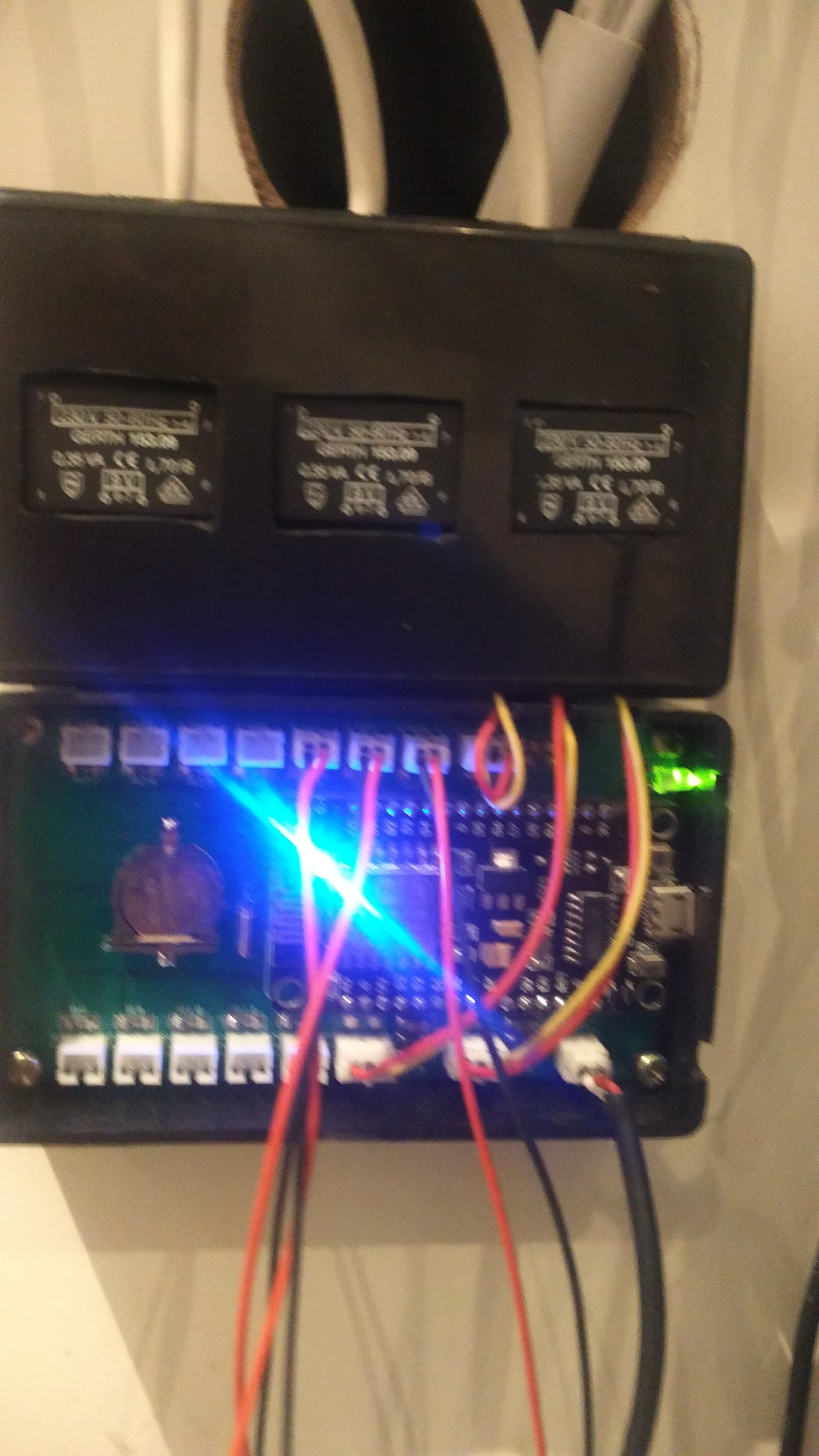
I’m not clear on what we are talking about here. Did you make a voltage adapter or an actual ESP8266 device with ADCs etc? Do you have a picture of the unit that is experiencing these problems?
I know. it was just as side related question.
My main problem in the end is the fact that Iotawatt gives higher readings when consuming and also higher (in absolute sense) when feeding the grid. This shift in measuments can’t be explained with number of windings. (i think).
OK, that’s a whole different story. I’ve changed the topic of this post to Homebrew and changed the title to indicate problems with a device that is not an IoTaWatt. IoTaWatt is a trademarked name that indicates a genuine product that has been tested to be working and accurate. It’s fair to say that you have a device that runs the IoTaWatt firmware, although I don’t know what version you are using or what if any modifications have been made.
This isn’t meant to diminish your efforts in any way, but the problem was presented in an unqualified way as a problem that others might see possible with the genuine package. You are in uncharted waters.
There are 42 combinations of phase assignment and CT orientation possible in a three-phase installation - only one of them is correct. It takes discipline and a methodical approach to get it right. At this point I have no idea if this is a three-phase problem or a fundamental problem with your device, or both. Others have built their own unit and are successfully using them with three-phase. It can be done. But the questions that I was asked indicated a better understanding of both the hardware and firmware.
So at this point, I wish you well, but this isn’t a project that I want to get involved in. Maybe someone else with more time will jump in.
Hi, I am sorry. it wasn’t my intention to make that impression. I just asked in the support section for some pointers. I thought it was already known that it was a selfbuild version (and it was, because you found my other postings.). I am running the latest Alpha 2-3-18. I made no modifications in the schematics. Other than 2 extra build in voltage adapters and different connectors. I understand you are a busy man with this great project but maybe you can point me in the right direction. . I paid very precise attention to the connection of fases and orientation and am convinced they are ok.
What happens for example if the reference voltage zener has another value?
Other than what? The voltage reference shunt can be any value less than 3.3V. There is a default in the firmware and you can override with a different value in the config file. This was actually covered in a recent post in the Homebrew topic.
The only component that I can see in your picture that is the same as a production unit is the battery. Understanding these things and troubleshooting your creation are all part of the DIY thing. I’ve provided schematics and open-source code for the DIY community, and if you want to build your own, you take it from there.
Even production IoTaWatt can have defective components or PCB issues. From what you are telling me, I don’t get the impression that you have even tested the unit to see if it properly measures a single-phase light bulb. Instead you’ve connected it to three-phase, with your own direct reference modifications, and then ask me why you don’t get the same results as your service meter. The simple answer is that I don’t know.