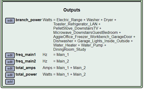
In my load center, the sum of main_1 and main_2 power should be greater than the sum of my 12 branch circuits power, but it’s not. Could it be my voltage reference transformer?
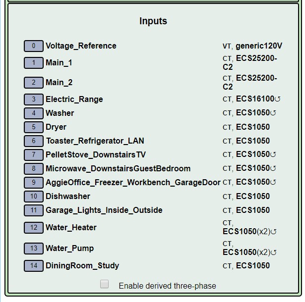
My Electric_Range and Dryer are both 120V/240V. So I use one CT for each of these circuits. Both red and black wires are run through the CT in opposite directions to measure the total power for the circuit.
My Water_Heater and Water_Pump are both straight 240V. One CT for each circuit. Only one wire is run through the CT and the firmware multiples by 2.
N[quote=“Agnes, post:1, topic:1050”]
In my load center, the sum of main_1 and main_2 power should be greater than the sum of my 12 branch circuits power, but it’s not.
[/quote]
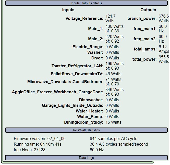
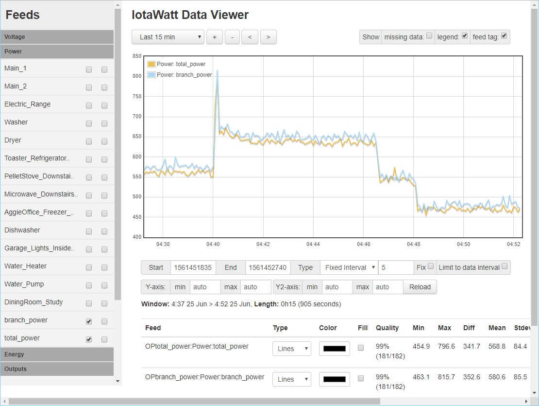
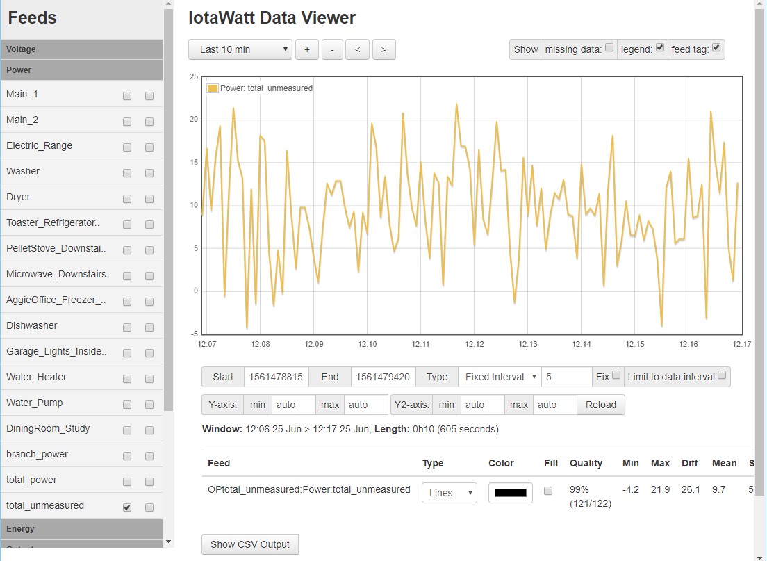
When you say it should be greater, do you mean that there are additional individual loads that are not being measured? Because right now that appear to be within about 2%. The snapshot in the status display differs by 3%, but when I look at the mean power over 15 minutes in the graph it’s about 2%.
So the question is whether you are expecting these to be equal, or are there other unmeasured loads?
Any difference is probably not a VT calibration issue as both the mains and individual circuits are using the same reference, so it would be a wash. If you were comparing to your meter, which is something I would recommend you do, then voltage calibration could cause a variation.
But a voltage difference between the two legs could be contributing to the variation. In the snapshot display above, none of those 240 loads appear to be active. There is an imbalance between the two legs. It’s still relatively low power, but if your neutral is long and/or has a lot of resistance, it could create a voltage difference between the two legs that can contribute to this variation. One easy test would be to plug the VT into a socket on the other leg and see if the variation goes the other way.
Another possibility is that one of the mains CTs is not seated fully. Those clamp type come with small squares of paper between the core mating surfaces that usually just fall out when you open them, but sometimes remain and reduce the readings. I don’t think that’s what is happening here unless you do have other unmeasured loads and expect the mains to be yet higher. But easy enough to check.
UPDATE: just looking at your other post this AM and recall that you are using a 240 volt reference transformer. So the suggestion to plug the VT into the other leg is of course not applicable. The idea of a voltage imbalance between the two legs is still possible, but probably not causing this variation.
Solved. When I put the front cover back on the load center, it slightly opened the CT clamp for mains2. Not much room in there. After fixing this, now the total unmeasured load is mostly positive, and it’s about what I expected.