I just got a “European bundle” (+ a few extra CTs), and have followed the setup guide until the CT configuration part. But when I click the CT around a cable, I see no power draw.
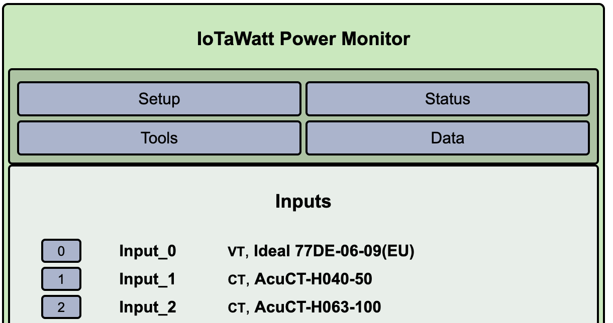
I’m just testing things, so I’m clamping “random” cables, but I’ve tried a few that have significant load (a couple of servers and most of the networking equipment). Since we have three phases here, I also tried clamping it around the same extension cable where I also plugged in the VT, just to be sure it was on the same phase (with a few other things plugged in as well, to be sure there was at least a few 100 Watts power draw). I’ve tried both the 50A and 100A versions I have (with the 50A version in input 1, model AcuCT H040-50, and the 100A in input 2, model AcuCT H063-100).
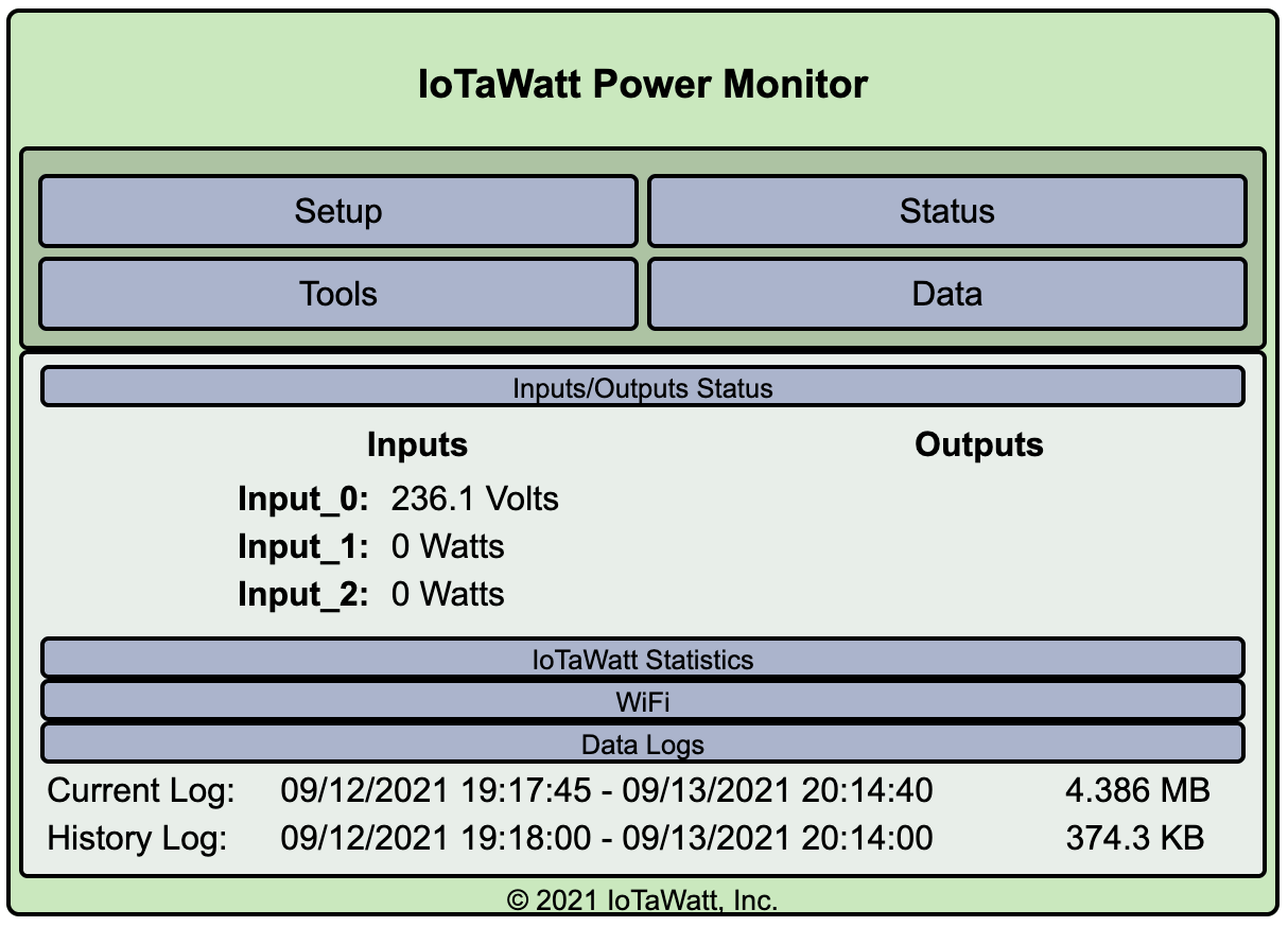
At most, I’ve seen the input briefly go up to 3-5 Watt, just as I closed the CT around. But only for a second or so while closing it. And only for the 100A CT, I see nothing for the 50A CT. I’ve tried attaching the CTs both ways, and with or without the “Reverse” box checked. The voltage is measured just fine, it seems (though I didn’t calibrate).
From here, I’m not really sure how to troubleshoot. I followed the guide pretty much to the letter, the only exceptions being that I chose the Ideal 77DE-06-09(EU) VT model, since this is what’s printed on the version that came with the kit, as well as chose the corresponding correct models for the CTs as mentioned above.