Hi!
We have really high electric bills and would like to understand which circuits the excess is coming from, as well as monitor things going forward. That said, the electrical set up is a little complicated so I wanted to ask the experts before I purchased all the CTs  .
.
What I know for sure:
240V from the street, plus we have a generator as backup for when the power fails.
We have 2 main panels, and a sub panel for the pool (I don’t care to monitor specifics on this, usage from the main panel is fine).
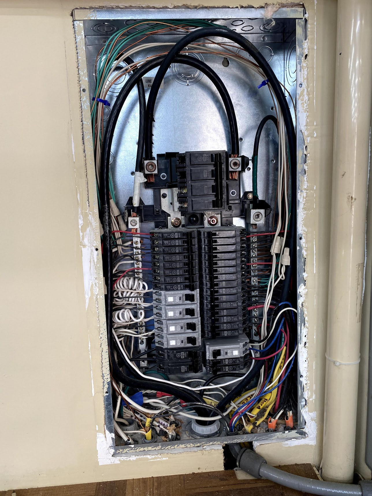
Panel 1:
For this one we want to measure:
- The main: 4 200A breakers up top are throwing me a bit for a loop, does that mean we would need 2 400A CTs or is it the standard 200?
- the hot tub (bottom left, double 50s, but it doesn’t look like it has a neutral) < so I believe I could get away with one 50A CT and choose the double option?
- 2 sets of AC both on 30A breakers, also doesn’t look like neutral so same as above I believe
- Oven - 2 sets of 20A breakers no neutral, so would need 1 50A CT
- a few individual circuits that would simply need 1 50A CT each
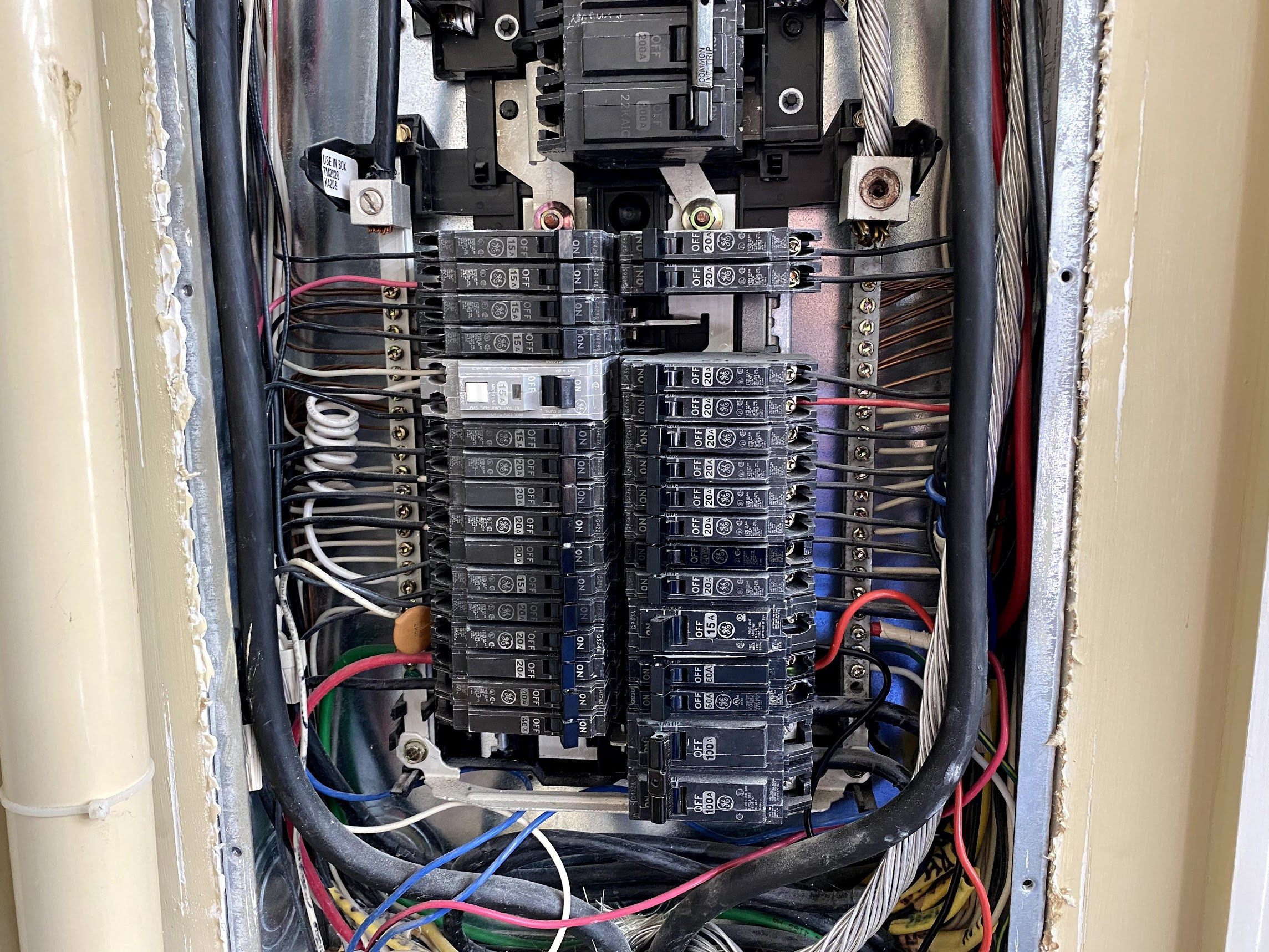
Panel 2:
For this one we want to measure:
- The main: 4 200A breakers up top (I assume same as the answer for the other panel
- One individual circuit that would need a 50A CT
- The Pool subpanel connection on the bottom right. This one I am unsure if I would need 2 100A CTs or I could get away with just 1 (I don’t think the neutral is connected there?)
Last, is there a limit to the number of the high powered CTs I can have in a single IoTaWatt? Would I need to have two just because it is two breakers or could I keep it to 1 as long as I have 14 or less CTs?
Thank you!!!
Edit: Happy to provide additional pictures if it will help
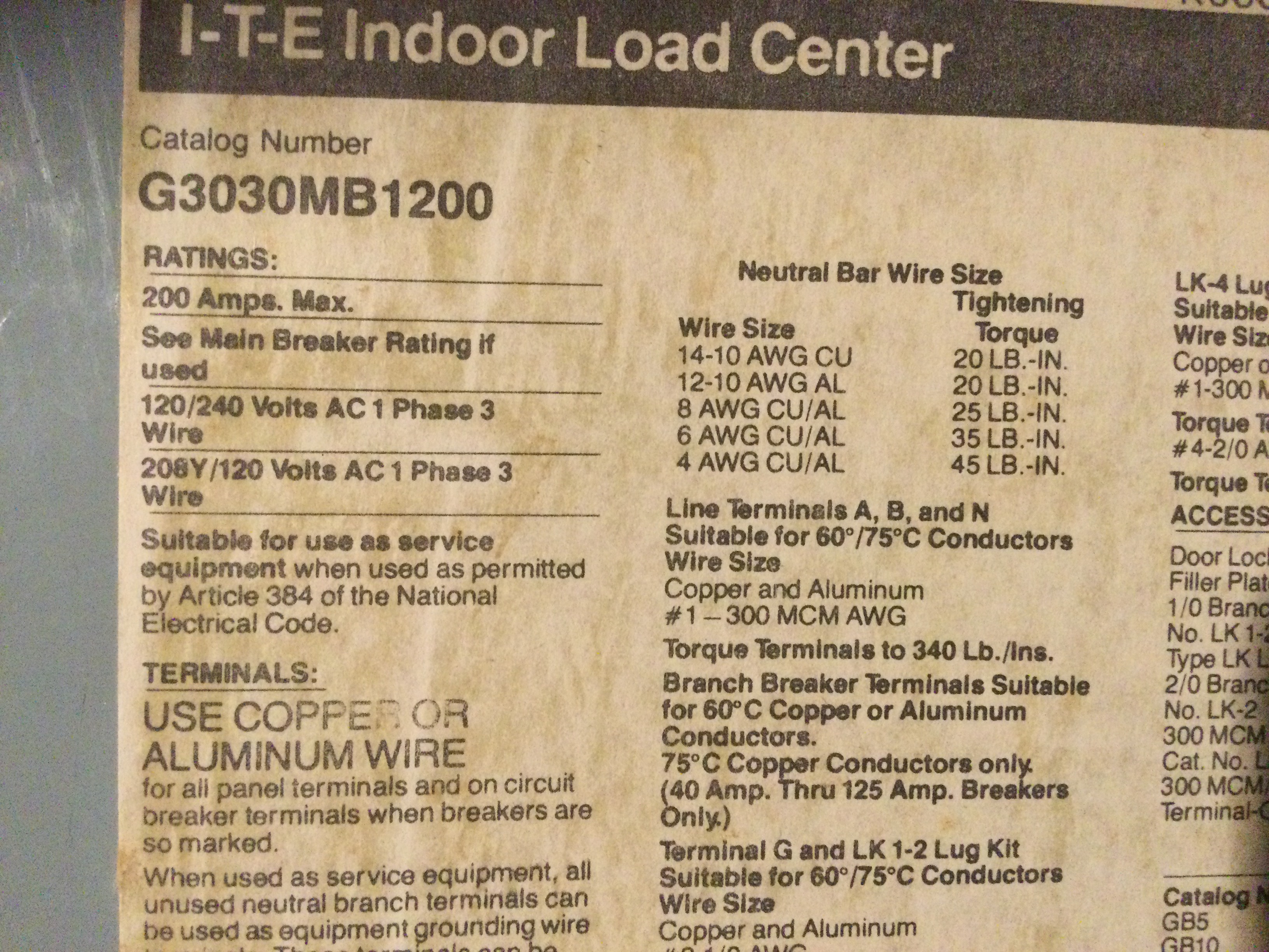
I believe those mains are 200A, but you could check with an electrician. Also, the load center should have a nameplate with the maximum current rating. Should be 200A, if not better to double check.
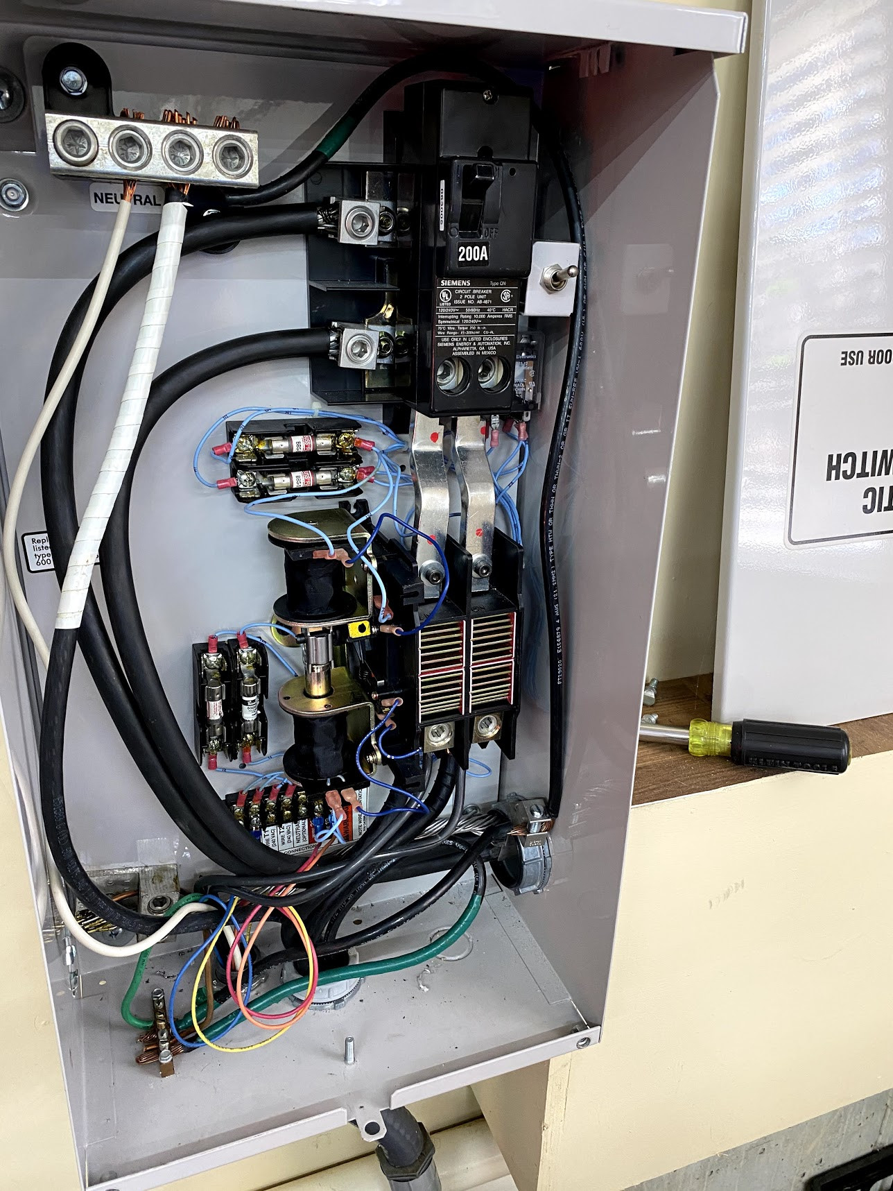
Sounds like you know what you want to do. You seem to understand that you can use one CT for a two-wire 240V load and need two for a three-wire load. There appears to be a pretty fat red wire with white tape on the right-side neutral bus of the first panel. You need to figure out what that’s all about. If you start out with a “floater” 50A CT, you can move it around to measure the other conductor of a suspected three-wire load. Graphing the two after a duty cycle will show if there is any difference caused by a neutral.
No. The CT does the work of stepping down the current. If sized properly, they will max out at a safe 50mA. There are industrial plants with a full load of 400A and 600A CTs. No problem.
You do not need two unless you want to connect more than 14 CTs (10 after the mains) or the panels are too far apart for practical connection of the CTs.
Thanks for the reply!! The panels are basically right next to each other so distance isn’t a factor. The electric company’s box which I assume is the load center shows 200A.
First panel or second panel? I’m seeing one in the second now that I am guessing goes to the pool (sigh). Thanks for catching that!
Last question (I hope  ), Can I use just one VT tester or do I need one for each circuit?
That looks like very thick cable for 200A service. The cable looks to be at least 500MCM. They normally use 4/0 for 200A service. But, I have 350MCM cable from the transformer to most of the way to the house, but it drops down to 4/0 at the meter. The meter is usually labeled to the maximum. Mine says CL200 (which is class 200 amps).
You only need 1 VT, since you have single phase service.
There are two 100A breakers. Do they go to the second panel?
The two 100A breakers go to a panel for the pool.
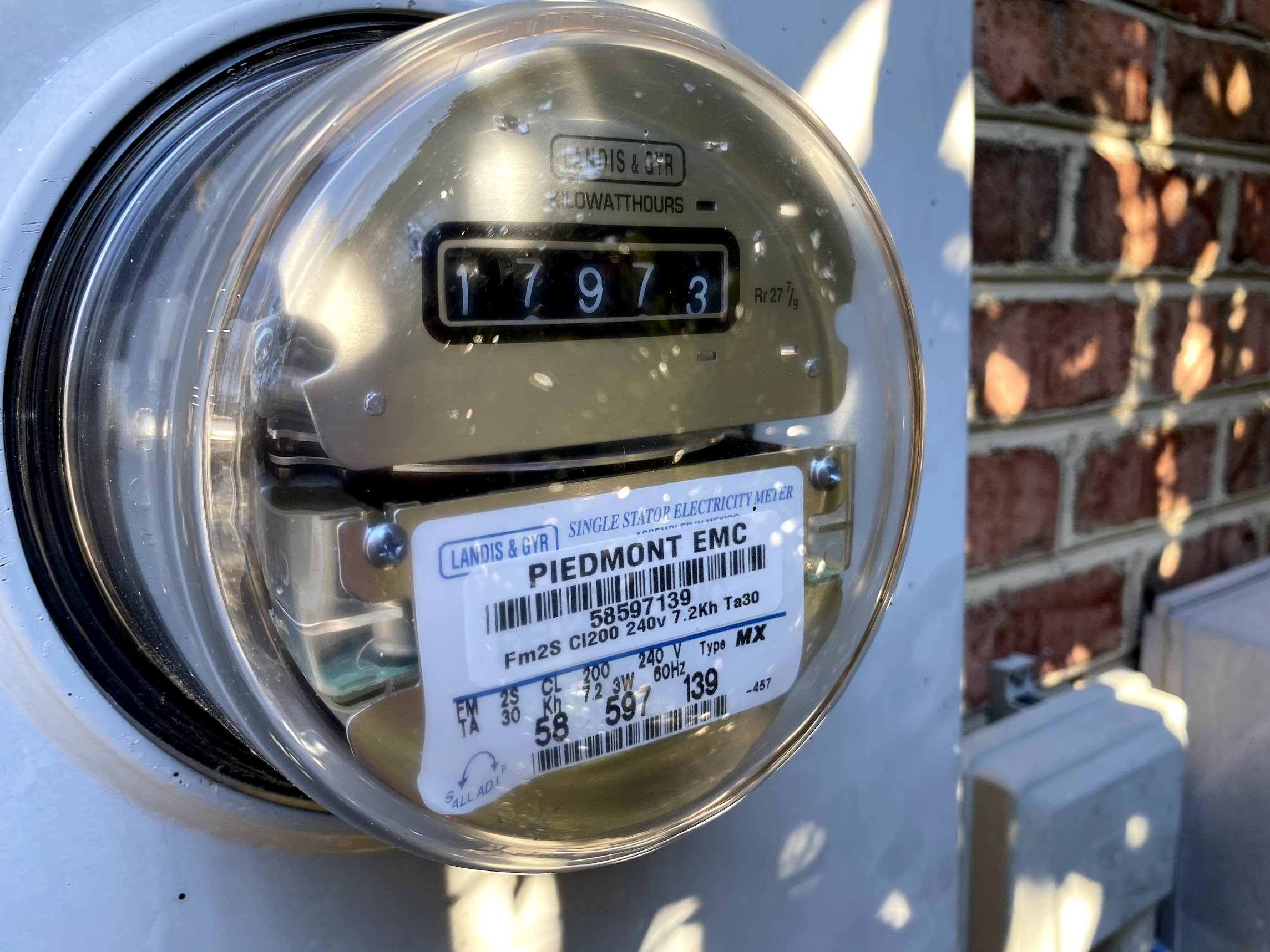
The meter says Cl200 as far as I can tell. There is a generator that kicks in if the power goes down, could that provide higher than the meter would? And if so how do I figure it out?
I will say, the people who built this house tended to go a little overkill on things 
Pic of meter:
A “load-center” is a fancy word for your
breaker-panel. There should be a nameplate on the inside of the door that states the maximum rating:
I’m pretty sure it will be 200 Amps.
In any event, 200A is 48kW. That’s a lot of power. You would be hard pressed to actually use that much. You would also be hard pressed to find a generator that exceeds that.
I’d recommend using the 200A. Once installed, you will be able to see what your actual Amps are.
1 Like
Yeah, that is a standard residential size meter, which is rated for 200A. Unless you have electric resistance heat, you are unlikely to get anywhere near close to the maximum. The main wires are much larger than what is “standard”. It looks like you have two service entrance panels, each of which can (but probably won’t) draw 400A (@240V). That is way more than the meter is rated for. But, it also depends on what the meter is connected to. My house is connected to a 25KVA transformer, which will limit the total amount of power that my house can draw. My old house (in the city) was connected to a 25KVA transformer along with 3 or 4 other houses. The power company knows that most houses don’t draw anywhere near the maximum amount of the service rating, so they technically “overload” them.
Not really seeing how your generator is hooked up. Does the cable at the bottom of panel 1 go to the generator?
At my house, I have the main panel which is the service entrance and gets power from the meter. There are a few non-essential circuits in that panel and a 100A breaker that feeds the next panel. This panel is the generator transfer switch and load center. The input of the transfer switch gets the feed from the main panel and the feed from the generator. The output of the transfer switch goes to the local bus/panel and the next panel. This last panel is really the “main” panel. The majority of the house is on it. There are also a few circuits on the generator panel. I have CTs on all the big items.
My typical peak usage in a 24 hour period is ~45A and ~9KW, but this is typically only for 2-3min (which is how long my sump and well pumps typically run). The biggest peak I have seen in the last 6 months is 69A (all at 240V). This was when both pumps were running along with pretty much everything else.
So what does the electric company say your daily usage is? Mine is in the 30-50KWh/day range.
The generator is actually a third box next to these two! Our best guess is it runs itself into these same panels back behind the walls and when the street power cuts off this switches over and uses the same wires into those boxes. We actually aren’t certain if only one or if both boxes are powered by the generator, we’ve never had to find out! (Only been in this house about 2 years).
Looks like our average daily is somewhere in the mid 40s most of the time, but looks like september hit 105A average O.O.
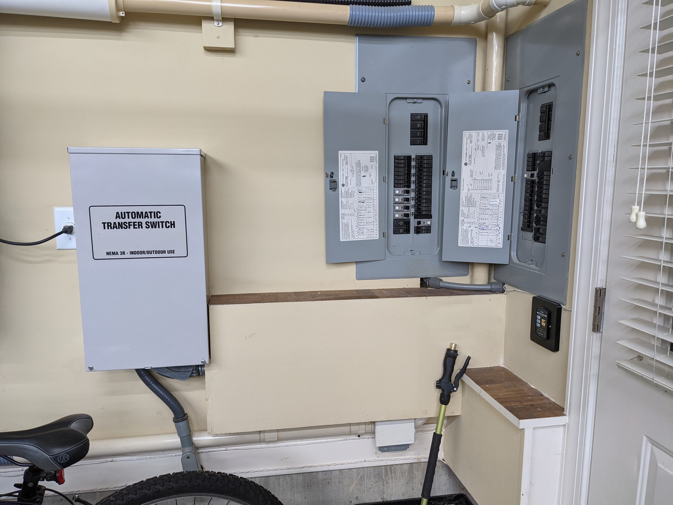
It would probably help if you took a big picture, ie not the close ups you have been doing, so we could see the big picture of how things are likely connected.
Your generator panel looks like it might be your service entrance. The medium size black wires coming in at the bottom center are the wires from the meter.
The smaller wires at the bottom to the left of that are from your generator.
The giant wires that go out to the right look like they go to a wiring duct/tray where they are probably split in two to feed both panels. The giant wires are sized for 400A service, but you only have 200A service (200A breaker).
So was that 105KWH or 105A. Assuming KWH, that is about 50-60KWH extra. That is a lot. The last person who had a problem like that had the water heater running constantly. It was heating the ground due to a leak in the floor heating system. I’ll guess that you have a pool heater you don’t know about it and it is running because it is cold outside. Turn off the pool house breaker and see if the meter slows down. To get 100KWH a day, it must be spinning very quickly.
1 Like
That was KWH. It was in September, looks like July was possibly that high but that particular bill wasn’t in front of me. My quick guess is A/C or hot tub. I know the heating in the house is Natural Gas, so it is unlikely that it was the heating.
The pool has a heat pump, it was off most of the time except one or two days, so it is slightly possible it was that, but I was pretty careful about keeping track of that. The pool breaker has been off on the pool panel side since the end of September. (Conveniently, also when A/C time went down).
Large view:
From Left to Right: Generator panel, Panel 1, Panel 2
ETA: Hot water heaters are on natural gas as well
So it’s the usual suspects: AC, Hot Tub, Pool. My money is on the HotTub. The IoTaWatt will tell the story.
The transfer switch has a 200A breaker, so everything downstream cannot exceed 200A. But i question whether it feeds both panels. Easiest way to find out is to turn off that breaker. If it does feed both, you can skip the mains in the two panels and just use a pair of 200A in the transfer switch. I’m guessing the transfer switch only feeds one panel. It’s not copacetic to bury a splice in a wall, so I don’t see how that mains feed turns into two.
I agree that would be easy to test, however the best time to test is unfortunately when the baby is napping, but that would cut off the sound machine in his room and risk waking him  . I would rather just get 4 CTs and measure both boxes! Plus, that would at least let us know if one side changes significantly to see when problems occur.
Take a look at where the output from the meter enters the house. It looks like it is probably behind the beige wall panel. While the wiring in the panels looks pretty good, it appears there is at least one code violation (I wouldn’t be very worried about it though). According to my recollection of the NEC, at the service entrance to a house, the ground and neutral are bonded together. At all other panels, they are supposed to be separated. Most panels have a removable bonding mechanism to support this requirement, which allows them to be used as a service entrance or as a sub panel. The electrician bonded the neutral and safety ground bars in the generator switch. It also has a 200A breaker (that looks service entrance capable) which matches the size of the meter installed.
Panel #1 has neutral and safety ground bus bars. They don’t look to be connected and I didn’t notice any mixing of connections.
Panel #2 has them bonded and there are both neutral and safety grounds mixed together. This is what is done at a service entrance. That would support Bob’s assertion that this panel is not connected to the generator. But, that 400A breaker is not consistent with a 200A meter.
Looks like you will have lots of fun figuring this one out.
Sadly, getting behind said beige wall panel would mean cutting holes in what looks to be 3/4" ply. It is sealed and glued on all sides and not nicely constructed to allow access