Hello there,
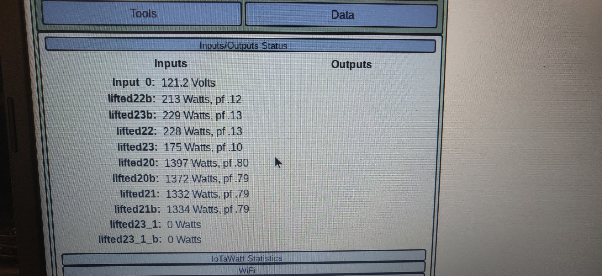
I’m trying to read the power off of four ant miners (sj19pro). Four of the readers give me values that I would expect. The other four values are very low. It doesn’t seem to matter what sensors or ports I plug into I get the same strange values.
Can some explain this to me? Are two of the miners really drawing such a low amount? What to the PF values mean?
Thanks so much,
Caleb
Can’t say without knowing more. It appears that for the two that with higher values, both the nn and nnb variants are the same. So what is the relationship between the two in each pair? Are they two legs of a 240V circuit?
Is your power 120V/208V or 120V/240V?
If you move a CT from 20 or 21 to 22 or 23, without changing anything else, what does it read? Does it read the same as the original CT on that wire?
Are you sure the two low power units are running?
Hello Overeasy,
Thanks for getting back to me. This is a 240v circuit. The two low power units are mining at the same rate as the two high power ones. Each miner should be running 2600 - 2800 watts.
If I move the CTs around the low reading stays in place. I’ve tried a combination of different CTs combined with different ports and have not seen the readings rise to match the higher readings. I highly doubt I’ve got two magic miners… If I do we need to take them apart and figure out what’s going on there.
Each port is configured the same way. I’ve made sure the direction of the CT is correct.
Cheers,
Caleb
One more thing. This is a single phase 240v circuit. I’ve got the CT around the blank wire.
Cheers,
Caleb
What do you mean by the “blank” wire? Each unit appears to have two CTs, how are they related? Can you show a picture of the panel with the CTs installed? Are the units two-wire or three-wire?
Sorry. Should have been black wire. I’ll take some pics of the CTs tomorrow and share them here.
Thanks,
Caleb
Based on the power factor readings, you don’t have single/split phase power. You probably have 2 phases of three phase. You really will need to show your CTs.
If you have 4 miners, why do you have 8 CTs?
If you are in a commercial space in the US, it is highly likely that your building has 3 phase power. Many times 2 phases are brought in to a panel to provide 208/120V. I am guessing that you are providing both legs/phases to one outlet and you have a CT on each leg. I think you also have them mislabeled. I would expect one leg of each to read correctly and the other to be wildly wrong. No matter what, since the miner runs on 200-240V, you only need a single CT for each miner, but you do need to install it on the same leg/phase that is powering the voltage reference.
@frogmore : That’s suppose to be single phase 240v. That’s what the panel is set up for. I’m in an industrial space that is three phase 208v at the street and 240v at the panel that is driving the miners.
I’m running 8 CTS because I wasn’t able to find documentation that the power supplies on the miners are balanced.
Each miner has two 240v inputs. I have one CT on each black wire going into the miners.
I’ll try putting the CT on the white wire and see what the reading is.
Thanks mate,
Caleb
There is no difference between a 120V/208V two-phase panel and a 120V/240V split-phase panel. Either leg will give you 120V, but the phase-phase voltage is 208V.
That’s hard to do. There is no way to directly convert three-phase to split-phase. You would need a pretty large and expensive transformer to do that.
I looked them up. I think they simply have two independent power supplies.
Read the docs about split-phase panels. Look at how the two phases usually alternate down the two sides. Typically the rows alternate, so a breaker on one side will be the same phase as it’s mate on the other side. Are the four high reading CTs all on even rows and the others on odd rows? I suspect you will find that.
The bad news is that the high and low reading inputs are both wrong. The good news is that it can be configured with derived reference to work correctly.
This is why I had asked the question:
You ruled that out.
If you can get a voltmeter and just measure the voltage across the two breakers in a pair to verify and get that picture of the panel so we can straighten this out.
@overeasy Thanks for the feedback. The panel is: 100KW 240/208V ASIC Mining Panel – ASIC Mining Panels
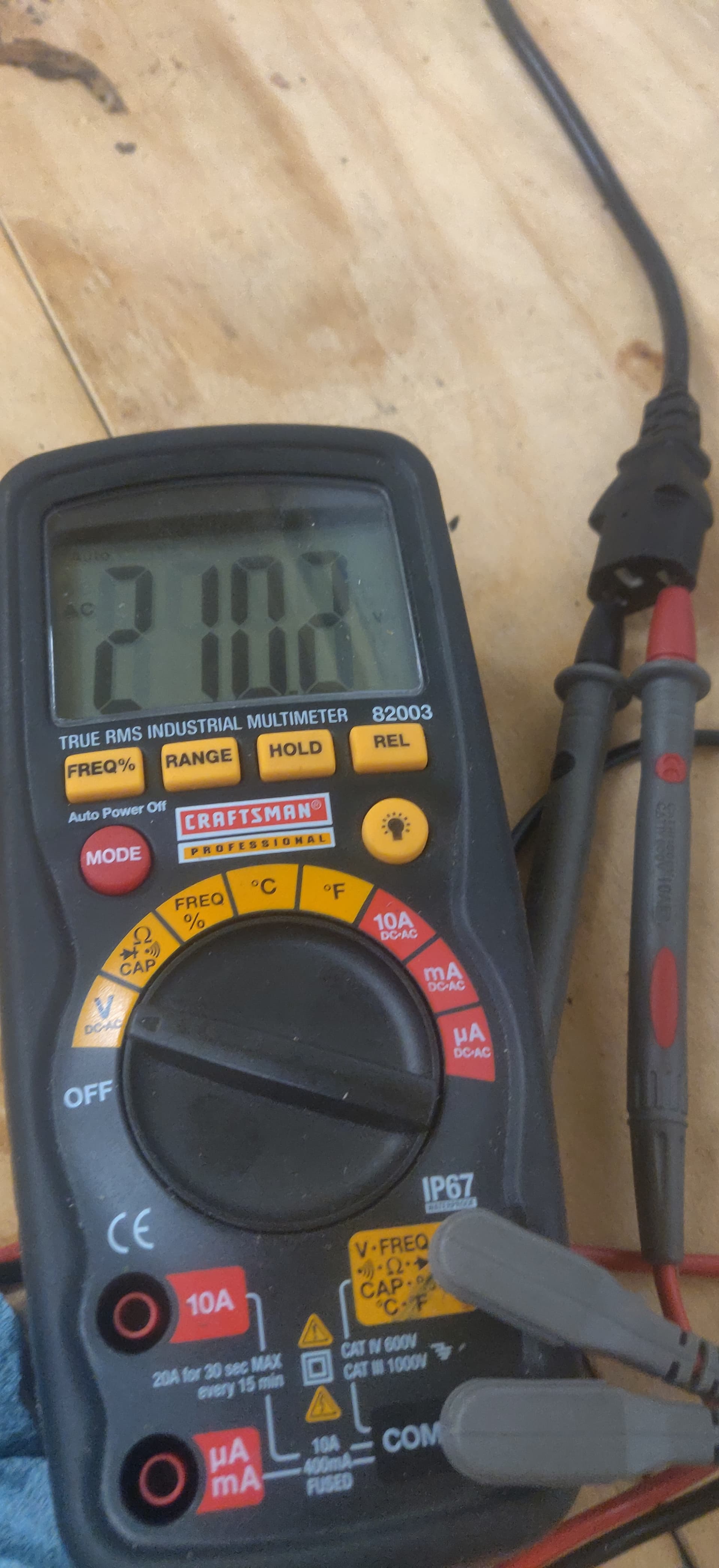
I’ll get voltage readings tomorrow.
Cheers,
Caleb
The info on the panel is not clear (not enough detail) but does indicate it is 3Phase 4 wire.
240V 3 Phase and 240V Single Phase • OEM Panels
You might have 240V 3 Phase Open Delta (3P4W) or could have 415Y / 240V 3 Phase 4 Wire (3P4W).
Since you do have some 120V circuit somewhere for your VT, I suspect you have the first one. Voltmeter will tell for sure.
@frogmore I’ll check with a voltmeter tomorrow. The panel does have a 120v PDU on it.
Thanks again,
Caleb
@overeasy I see what you are saying about the 240v monitoring. I’ll wire up a connector tomorrow and try that.
Cheers,
Caleb
You really need to understand the power that is coming into the panel. If you have the panel you linked, it is clearly 3 phase. It is highly unlikely that a big industrial space would have 208V3PH. 415V or likely much higher at the street (think 12KV or higher). There is probably a large transformer at the facility that takes the high voltage and drops it down to something like the ones listed here:
Preferred Standard Nominal System Voltages in the United States – Bruns Engineering
there is one called:
-
240/120 (240 V phase-to-phase and 240/120 V from a mid tap of one winding that is connected to neutral from a delta wound transformer or generator.)
That is 240V 3 Phase Open Delta (3P4W) from the link in my earlier post.
It is likely you will need to do the work to get derived phase and assign each of the CTs to the correct phase.
I’ve done some simulations and the higher Wattage at PF ~.70 would be consistent with a high PF power supply running on 208 with a 120V out of phase reference. I’m still at a loss to explain the low Wattage ~.10 PF loads. I’m thinking they may be the second power supplies of each unit drawing low power, but clearly more info is needed.
@overeasy You have been very helpful! Let me gather some more information; talk to the electrician that wired up the place and then we can solve.
Thanks so much,
Caleb
I’ve studied this a bit more and am increasingly convinced that you have a 120V/208V three-phase panel. Any 208V load can be connected to either A-B, A-C or B-C. Given that your loads are two-wire 208V loads, Any load that uses Phase A should be reading Watts correctly. Any load connected to B-C will show very low. It defies the odds that 4 of your eight loads are B-C, but is certainly possible and likely if the first breaker starts with B as in
B
C
A
B
C
A
B
C
The first and last 2 pole breaker would be B-C with one each A-B and C-A between. If the other four are in the corresponding positions on the other side of the panel, they would be the same. That’s just an example. There are other configurations that would produce the same result.
If you want to test this theory, simply check “Allow Derived Reference” in the inputs setup and then select phase B in the setup for one of the low reading inputs. If it comes into line with the normal inputs, that would be diagnostic.
The remaining possibility is that you have “high-leg” delta in your building. That’s pretty rare, and you have said the building is 120/208, but just to mention that in that eventuality there is a setup to measure that as well.
@overeasy
I checked this with a meter. This is a 3 phase 208v system. I’ll check the docs for setting up the CTs for this and let you know if I have another other issues.
Thanks,
Caleb
2 Likes
The setup for three-phase derived reference may be complicated by your reference voltage probably being connected to a 120V outlet that is not supplied by this panel. What is key is identifying which of the rows in your box is phase A, defined as the phase to which the VT is connected.
You can determine this by examining the current panel setup. As described above, the rows of a three-phase panel alternate sequentially as you go down.
L1
L2
L3
L1
L2
L3
L1
etc.
If you identify the four breakers feeding the correctly reading inputs, They will all have one of those phases in common. It doesn’t matter which of the conductors the CT is on, it only matters that one of the two rows is the common row. Let’s say it is L2. Then L2 is IoTaWatt’s phase A. Depending on your phase rotation, the others will be either:
phase B = L3
phase C = L1
or
phase B = L1
phase C = L3
If you have a picture of the panel with the cover off and note the four correct ones (or the four incorrect for tat matter), I can tell you which it is. After that, a simple experiment would determine phase rotation and the correct assignments for each input.
Once you know the phase A, B or C of each row. You will assign the phase of each input based on the two phase of the two rows of each breaker:
A-B
B-C
C-A
Place the CT on the conductor corresponding to the first phase of the pair (B in the case B-C.
NOTE: This post has been edited to include more detail and make the phase designations less ambiguous.
1 Like