Industrial 277V/480V three-phase

Over the past month or so, I’ve been working with the manufacturing facility to install an IoTaWatt on the primary service of the plant. They recently upgraded their service from 600A to 800A, so given the shutdown that would require, it was a prime opportunity to install some CTs and have the electrician install an IoTaWatt.

The first technical challenge was sourcing VTs for 277V. I found a 277V:12V model manufactured by Axis corp (AX-27750-H) that works fine. I calibrated three samples and added this model to the IoTaWatt tables.

The second challenge was selecting appropriate CTs. The service uses tandem cables for each leg, and they are pretty fat. In theory each carries half of the current. In practice I found that to be generally accurate although they are not exactly equal. I will present the data for that in a later post.

Since the conductors each carry approximately half of the total current, I elected to use individual 400A CTs on each cable and connect them to individual IoTaWatt inputs. Each phase uses two IoTaWatt inputs for a total of six. There are a few other ways to do it including using a larger 600A or 800A CT, or combining two smaller 600A or 800A CTs into one input with a splitter. I chose this because it is economical, offers the best resolution, and allows me to see if there is any imbalance in the parallel cables.

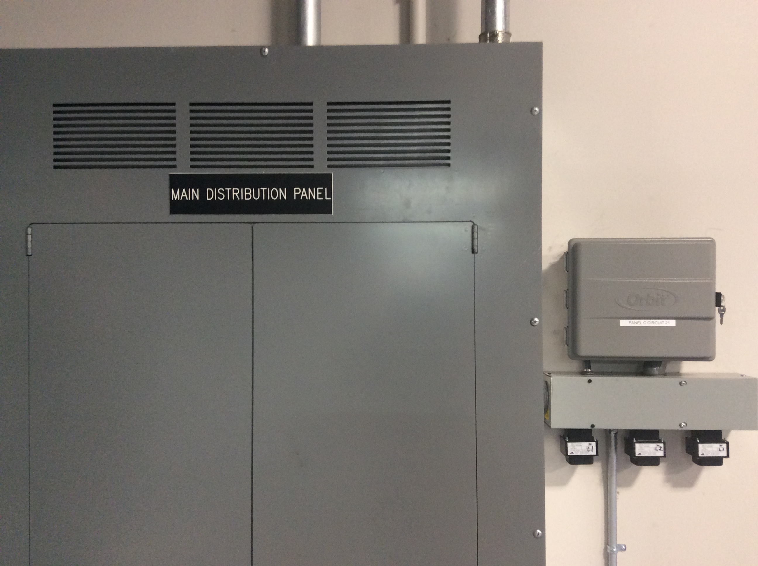
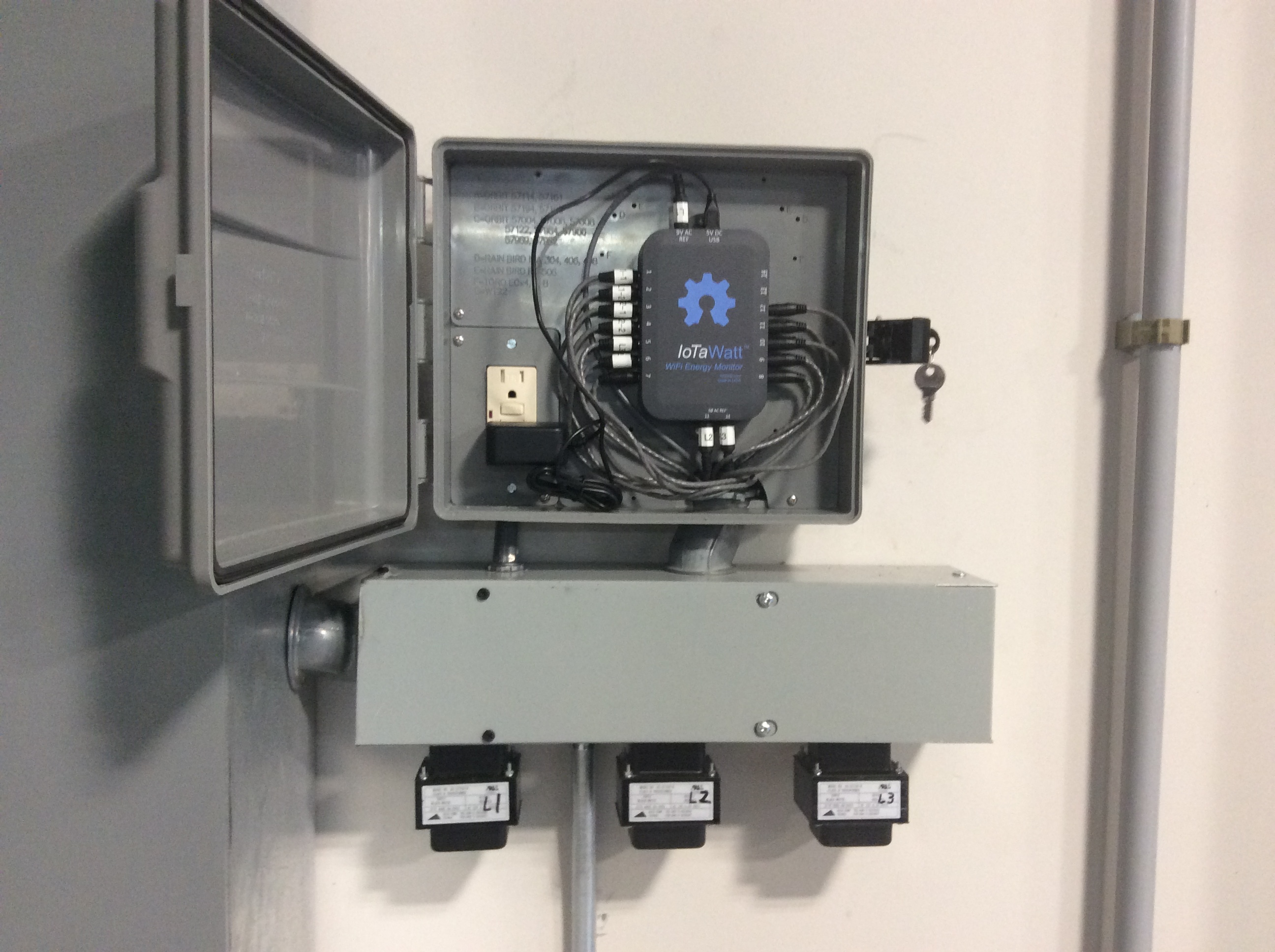
I was not present for the CT installation during the shutdown, so I don’t have pictures of that, but here is the installed unit. You can see the voltage reference transformers hanging from the lower junction box. The electrician did a very nice job. The plastic box is an Orbit sprinkler control box with 120V GFCI.

The IoTaWatt was powered up a few days ago, and I’m currently uploading to Emoncms to gather information. In a few weeks I’ll install influxDB/grafana on premises.

As a demonstration/learning project, I have several goals with this install.

  1. Demonstrate feasibility of using IoTaWatt for large industrial use.
  2. Develop metrics and techniques to help the plant better manage electric use.
  3. Investigate the relative merits of direct and derived three-phase in this environment

Objective 1 is well along. I found it relatively easy to provide the materials and work with the electrician to accomplish the physical installation.

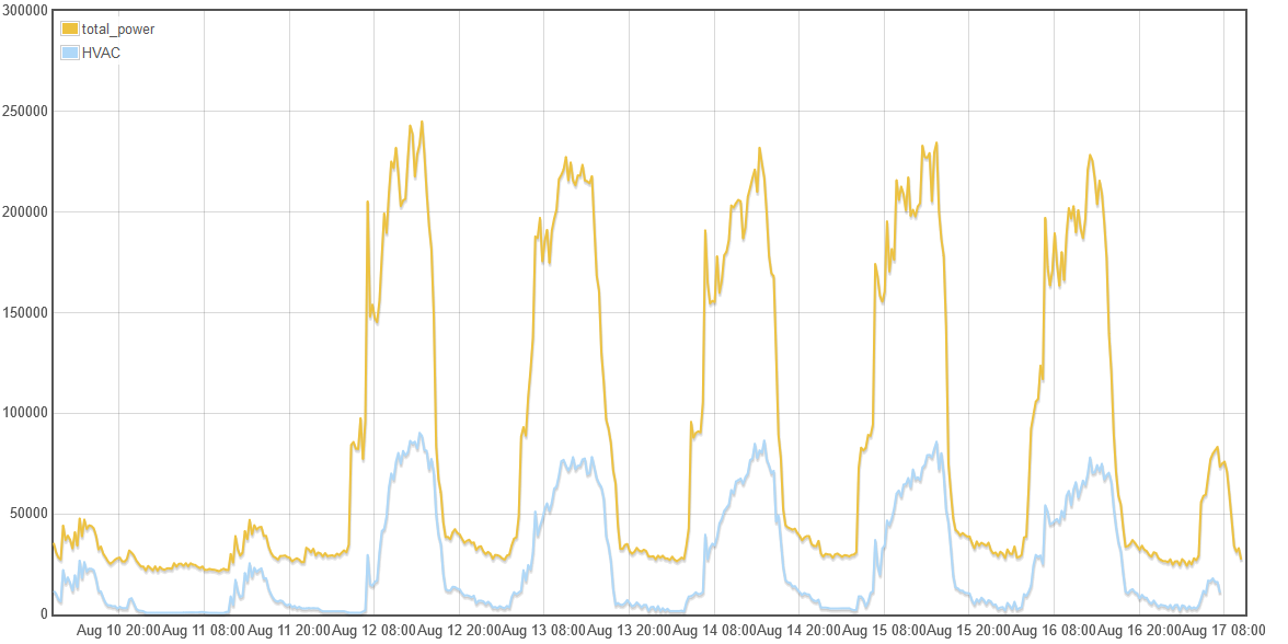
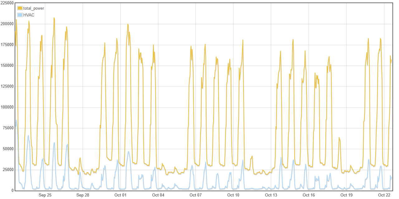
Objective 2 will be an ongoing process. I don’t know where it will lead. There are a lot of large loads in the plant. In addition to the mains, the electricians installed CTs on the beaker that feeds the HVAC panel. I suspect that is the major load here in July, but we’ll see in a week or so.

Objective 3 is now ongoing. With IoTaWatt, it’s possible to measure the mains using both direct and derived voltage/phase reference. For the L1 phase, they are the same. Only the L2 and L3 are derived. This experiment eliminates the CTs and loads as variables because it’s possible to configure the IoTaWatt to use any physical input for any logical input, so I’m using the same four CTs for channels 3-6 and 9-12 in real-time. They are the four CTs on the the L2 and L3 cables. I plan to run this for a week or so to gather data.

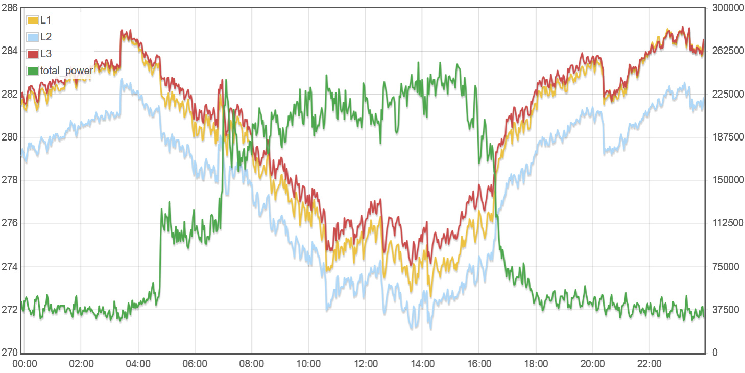
The voltage transformers have not yet been fine-calibrated, but here is a days worth of voltage for the three phases, along with the total-power plot. Notice that voltage drops about 2-3% during the day when the load is high.

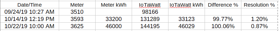
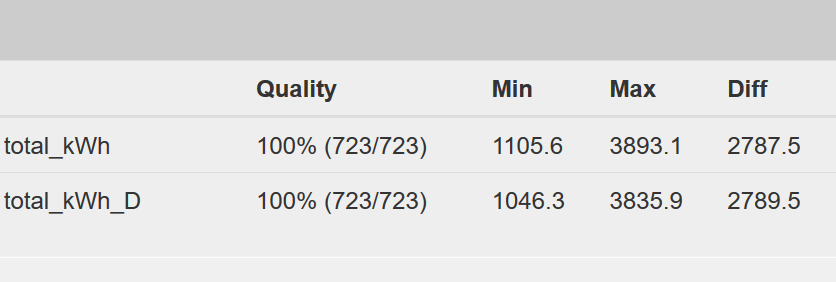
Now, lets look at direct vs derived reference for the past 24 hours:

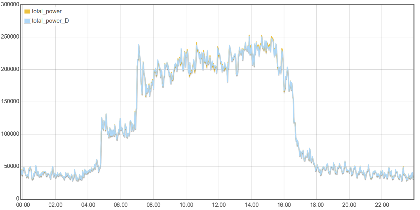
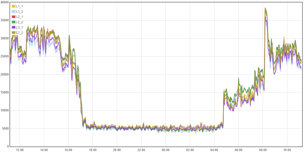
They lie right on top of one another. That’s no big surprise, but just how close are they? The answer is that they are within 0.07% as shown below. I was stunned. There was some individual variation: L2 derived was 4 kWh low or -0.4% and L3 was 6 kWh high or 0.6% resulting in the total being 2 kWh high. Looking back on the voltage plots, L2 voltage was lower than L1, and L3 higher, so that makes sense. We’ll see what happens after the voltage transformers are site-calibrated. One thing is clear: This installation would get very useful data with derived reference using only one transformer.


This will be an ongoing project, and I’ll post the the developments as they happen.

3 Likes

With a solid week of comparison to the utility meter, accuracy appears to be developing. I say developing because the meter counts 400kWh, and the system uses about 14,000 kWh/week. So the meter rings up 35 units in a week, and the corresponding usage is +/- 400 kWh.

After one week the meter counted 36 or 14,400 kWh +/- 400 kWh. The margin of error is 400/14,400 or 2.8%.

IoTaWatt recorded 14323 kWh for the same period. That works out to 0.5% variation, but could be anywhere from -3.2% to +2.3% with the meter resolution. It will take two and a half weeks (40,000 kWh) to get a baseline that is within 1% and more than a month to get the meter margin of error below 0.5%, which is closer to the meter spec of 0.2%.

Here’s a week of total usage along with the HVAC panel component (also 277V/480V). I suppose I shouldn’t be surprised that IoTaWatt is handling this in stride. It’s kind of like Heinrich Dorfmann in “Flight of the Phoenix”. There are companies making real expensive equipment to do this, but the “model airplane” design seems to scale just fine to 100x the power of a typical home.

After two weeks with the margin of error due to meter resolution down to 1.4%, the IoTaWatt now differs by 0.4%.
Meter: 28800 kWh (400kWh resolution)
IoTaWatt: 28698 kWh (1 kWh resolution)

Here’s an update on this project. There were a few interruptions unrelated to the IoTaWatt. The power supply GFCI tripped and I made a configuration error while removing the derived three-phase experiment. Nevertheless, the unit has been running flawlessly since September 24.

As of yesterday, October 22, the plant had used 46,000 kWh by their meter reading (400 kWh resolution). IoTaWatt recorded 46,029 during the same period - a stunning 0.06% difference! That has to be tempered with the reality that because the meter has 400 kWh resolution, the meter reading could be anywhere from 45,601 to 46,399 kWh, so the IoTaWatt is definitely within +0.9%/-0.8%, and probability says there is a 76% chance it is +0.5%/-0.4%.

As previously explained, the incoming mains are parallel lines with a CT on each line. So the total power is the sum of six lines. Here’s what that looks like for 24 hours:

At the same time, the IoTaWatt is measuring the load to the HVAC panel. In August, the HVAC was over 100kW at noon.

As you can imagine, when using 250kW, there’s a lot going on. The plant has numerous panels and transformers throughout. By example, the wave soldering machine is European and uses 230V/400V via a stepdown transformer from 277V/480V. IoTaWatt has no problem changing gears from one to another. In fact, if using derived reference, one unit could conceivable be monitoring circuits on 277V, 230V and 120V panels at the same time.

The next phase will start to break down usage to develop cost saving strategies. The tariff is also based on demand, so we will be measuring Var as part of the equation.

1 Like

really interested to see how this has developed Bob,

we are currently specifying a BoM for a client which has substantial loads distributed across a number of plant rooms. most circuits are sub 650A but the main incommers are 2000A (emoji of smacking myself in the face) we need clarity to see if they are wired in tandem but it is great to see you have done work with the external transformers and the CT’s

do you have interest in stocking these if we are to procure say 10? also on the 800A clamps is there a hard stop at 800 or will they loose accuracy beyone up to the 1000a range. i suspect peak load for the facility in question is way below 2000A

Hello @jonsand

I’m confident suitable CTs can be sourced. I can get any of these CTs with about a month lead time: https://www.echun-elc.net/Products.asp?BigClassID=81. Any unit that has a 50mA output option is available. It’s also possible to have the burden resistors changed to accommodate other CTs. The IoTaWatt firmware is designed to be able to do that.

I have a limited number of large CTs in stock. With a 2000 A service, I think it’s either multiple parallel feeds or bussbars. CTs are available for both.

Most CTs will go somewhat beyond their stated range without much loss of liniarity but they do start to saturate and phase shift and distortion start to effect the results. The major limitation is the input current to the IoTaWatt. The stated range is 50mA, and the absolute limit is about 58mA. Beyond that, while no damage would be done, the range is clipped and accuracy would fall off sharply. That range is a function of the burden resistor, so it can be changed. When you have more detailed specs, I can be specific about the options.

Great,

hope you are safe Bob, we have a PO raised but the lockdown has blocked us from getting it releases so will let you know the second it happens and we can get an order in :slight_smile:

1 Like