New install, shows MegaWatts being used! - RTM example

RESOLVED: issue due to serious documentation omissions.

Received full kit today, pair of AccuCT-H063-100 for the mains, AccuCT-H040-50’s for branch circuits.
Device seems to require ports 0-1 to have the AccuCT-H063-100’s. With port 0 empty all other readings go to 0.
Port 0 came set up with 0 burden resistor, all others were pre-set to 20.
Is this a defective device?
I have all used inputs set to the appropriate AcuCT-Hxxx device yet port 0 shows over 100,000 watts and port 1 always over 6,400 watts, pretty sure my office is not using the 4,500 watts showing:
|Main_0:||100716 Watts, pf: 1.00||—|---|—|
|Main_1:||6200 Watts, pf: 0.80|
|Furnace_4:||20 Watts|
|H2O_8:||5 Watts|
|Office_14:||4431 Watts, pf: 0.85|

I swapped inputs 0<->1 and the insane high reading remains at input-1 so the issue is not a defective AccuCT-H063-100.

Am I supposed to have some kind of different sensor for input-1 that is not supplied in the kit???
In screen shots of other peoples installs I see input-1 shows voltage instead of power.
Zero documentation on this that I can find, can someone please help?

Input 0 is the VT. The CT inputs are numbered 1-14. Can you post a screenshot of the inputs setup display?

Step by step setup documentation at http;//docs.IoTaWatt.com.

Thanks for looking.
I already figured it out, too bad about the zero useful documentation.
To help the next person: Input-0 is NOT configured from the factory.
Also: Input-0 will NOT be configured like ANY of the rest of the inputs.
Also: Input-0 MUST be configured somewhat correctly for any other Input to work.
— Example of how I got mine to look like it’s working –
Make sure ‘Burden Resistor’ is set to 0 for Input-0.
Then in ‘Input Configuration’:
Set Type to ‘VT’
Set Model to ‘TDC DA-10-09-E6’ (No idea what that is referring to)
Select ‘calibrate’ and adjust the ‘calibration factor’ until the displayed voltage is at or near your measured AC voltage. For me that was a factor of 10.61.

To reiterate the best advice I can offer.

This has worked well for thousands of satisfied users.

5 Likes

I have personally been thoroughly pleased with the ample documentation on the setup of new Iotawatt devices.

I personally didn’t have an issue setting it up. I think @ATuttle sounded very frustrated, but having been on both sides of many usability studies, I understand the feeling. Sitting through a usability study of something that you have created is frequently a humbling experience. Things that I think are obvious to the most casual observer are not, to many people. When I am on the other side of the one way mirror, I always try and give lots of feedback of how confusing the experience is, and, in particular, what I don’t understand.

I took a look at the documentation. It REALLY needs a quick start. Many people are not going to wade through the clunky UX (it requires too much clicking) of the documentation. There are no pictures.

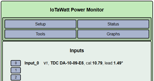
From a HW perspective, the VT uses a different connector than the CTs, so it would be hard to get those wrong. It is not clear what @ATuttle meant when they said input 0. Since I don’t think it is possible to actually plug in the CT to input 0 (on my IotaWatt it would require an adapter to do that, barrel vs 3.5mm TRS). I am assuming it is this page that caused the problem:
image

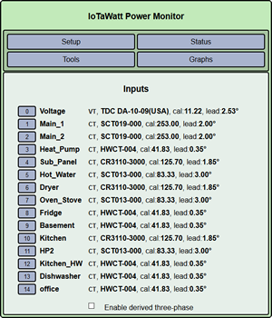
This page exposes the internals of the device to the user. I don’t recall having an issue with it, but I can see how it might be confusing to someone. In the normal use case, input 0 is ALWAYS a VT and it is a mistake to configure it as a CT. I am not sure there is a use case where it makes sense for input 0 to be CT.

I am guess this is the mistake that @ATuttle made. I haven’t looked at that code, but since you always have to have a VT and generally channel 0 (on the internal ADCs) is “hard-coded” in hardware to be one, do the same thing in the SW. Make a visual distinction and make it clear that this needs to be set to something.

But, it comes back to resources. Writing really good documentation is hard and generally not something most developers consider the “fun” thing to do. The documentation has certainly been good enough for many people to successfully set up their system. Perhaps @ATuttle would be willing to share what about the documentation did not work for them. Looks like post #5 in this thread is it, and this is what I said about the possible confusion about the difference between a VT and a CT and the fact that you MUST set up a VT first to get ANYTHING to work. The documentation on that is anything but clear. I did not have an issue with it, but I came to this with a long background in using these types of devices and knowing exactly what they need to work. At a minimum, I would add some words to the quickstart that said if you do nothing else, you must

  1. Plug in the USB power
  2. Plug in the AC reference transformer VT
  3. Plug in one CT
  4. Set up Wi-Fi
  5. Configure Device
  6. Configure VT
  7. Configure CTs

You actually have sections for all of those things, but the important details are easy to miss if one is in a hurry (and/or doesn’t like reading a lot of text). I would put about a sentence for each of the items in the list and put a hyperlink to the details for each of the steps. I think if that had been in place @ATuttle would have figured out what needed to be done much quicker and with far less stress.

Let’s just let this one die on the vine. The claims made were simply not true.

It definitely is.

The documentation makes this clear:
You should have installed the device with a 9 Volt AC voltage reference transformer (VT) plugged into the channel zero power jack. If your initial configuration has this channel pre-configured, your LED will be glowing green because it’s rhythmically sampling that voltage.

It comes that way.

It is pre-configured that way. Documentation also explains clearly:

A list of all of the inputs will be displayed. The first entry will be input 0 and a default VT should be configured. Check to see if it’s the same as your VT model. It’s OK to unplug the VT to check the model number printed on it.

Here’s the picture from the docs of the offending display @frogmore cites.
image

The standard calibration for that VT is 10.79. 10.61 is almost 2% off. With no idea what he calibrated against I have to say the several highly accurate meters that I have show consistent accuracy with the standard value across many production units and individual transformers that I have had on the bench for whatever reason.

This is just bad information from an unreliable source. Lets not try to smooth it over. It is not helpful.