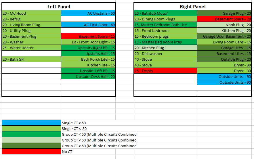
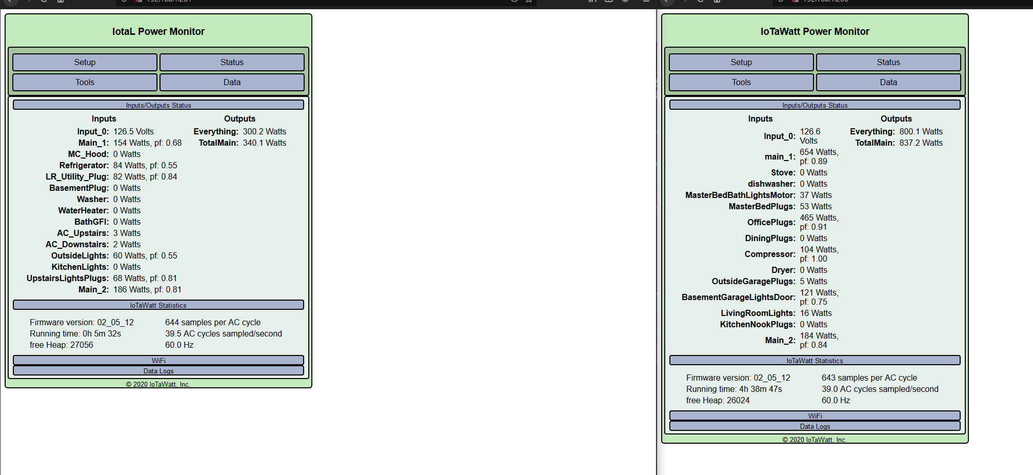
Greetings everyone. My energy bill been sky rocketing lately so as an attempt to get things under control and be more proactive with energy usage, I bought ecobee thermostats throughout house and ordered 2 iotawatt units. Since each unit only has 16 available inputs (2 reserved for mains), I can’t just monitor everything. This was what I was thinking layout wise:
Any thoughts on that layout? The only thing I can think might be worth switching around is on right panel I have individual legs monitored on Stove, Dryer, Outside HVAC units. Might be able to gain 3 inputs by just doubling a single leg, and using them where they might make more of a difference in the right panel?
EDIT: A question I forgot to ask, I plan on installing these units just inside the panel and putting a breaker in just for them. I got a pretty beefy wifi router that reaches almost 2 houses down so don’t think router range will be an issue, but will the ESP chips get their wifi through the panel doors? Anyone tried this?
Without getting into a lot of detail:
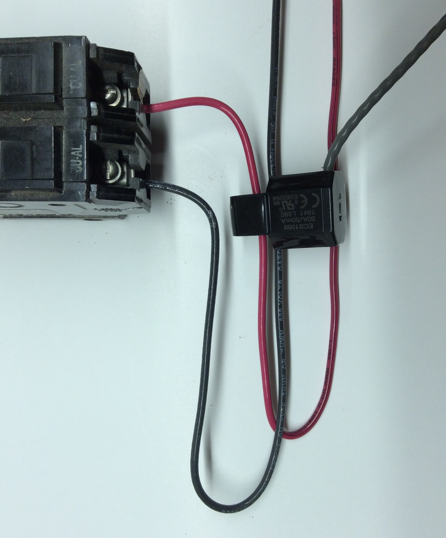
In general, you can monitor a three wire (Two hot + neutral) using one CT if you can pass the conductors through in opposite directions. You need a CT with nearly double the breaker value.
If the 240V load doesn’t have a neutral, you can use one CT and “double”.
Where you have multiple circuits combined, you can do it by combining the CTs with a headphone splitter, of by simply passing multiple conductors through one CT (or any combination of the two). You do however need to be sure that the conductors from one leg pass through in the opposite direction. This is where it may be useful to use two CTs combined with a splitter and combining the conductors from each phase into different CTs.
By creating an output for each panel that subtracts all of the measured loads from the mains, you effectively measure the combined load of those circuits. So in each panel, where you are combining 4 loads but measuring everything else, you can get that measurement by the process of elimination.
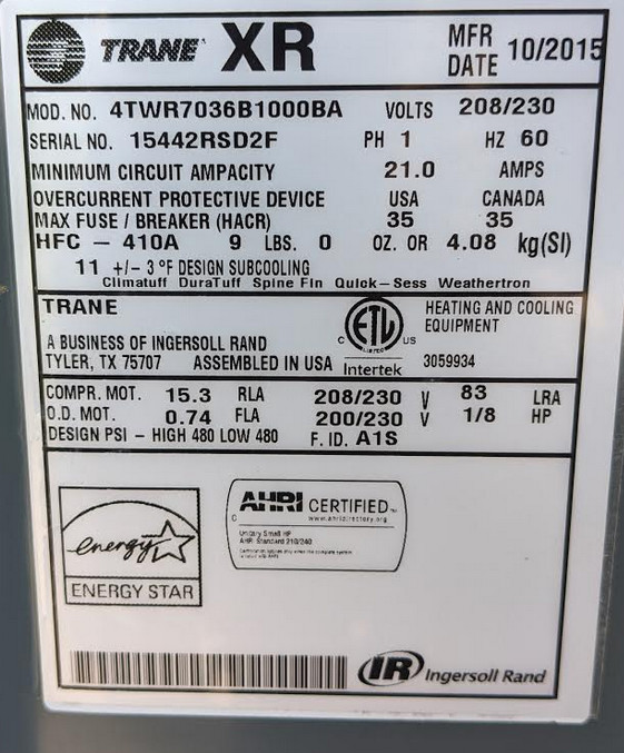
90 Amps is a big load for a condenser. I’d check the nameplate on those.
It’s two condensers on a single breaker. Two of these:
I didn’t think to combine red and black into a single CT. That might be what I’ll do then so I can split apart some of the other grouped circuits for more detail. I read that in the IoTawatt documentation, but I forgot all about it when specing out the CTs to order. I’ll do that then for the stove, dryer and outside units so I can gain 3 more inputs to split apart other groups.
Thanks.
Schematic for that unit indicates it is a two-wire unit, so you only need one CT with “double”. The nameplate specifies maximum overcurrent 35A, so my guess is that there are breakers elsewhere for the individual units. In any event, a single 100A CT should do it for those.
Odd, I might have to trace this out and see where all it’s going. It might be supplying something other condensers then. They are using red and black wires and looks like they followed convention (2 blacks for circuits with no neutral, black/red for circuits with neutral).
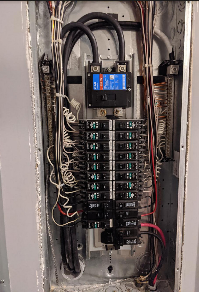
Left Panel with double breakers no neutral
Right Panel with double breakers with neutrals
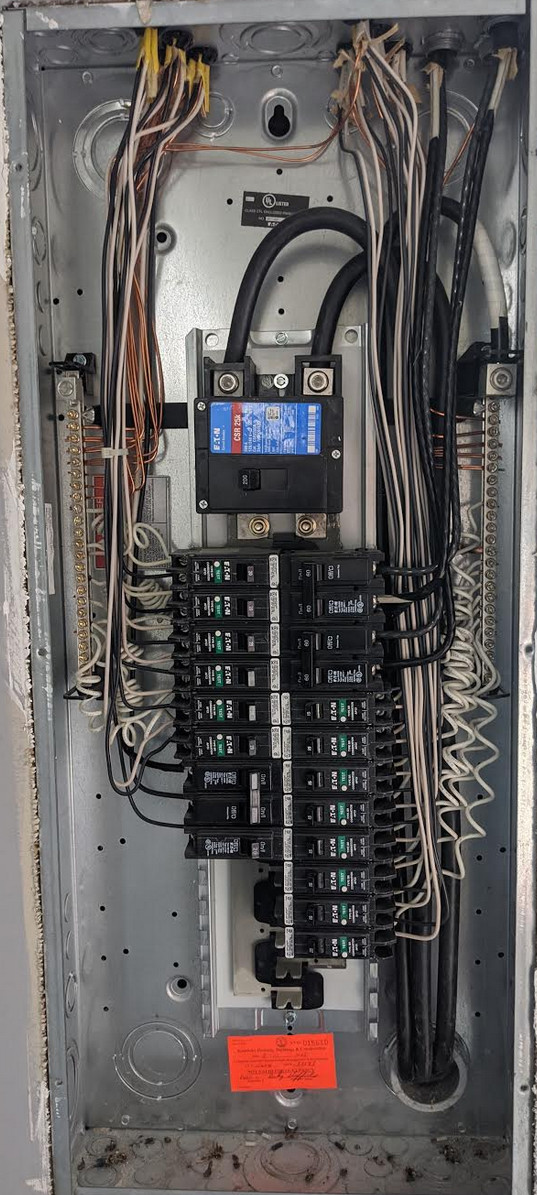
I see that all of your 120V circuits are arc-fault interrupters. They have both the hot and neutral running to each breaker, so it’s easy to identify the neutral for any circuit. Going down each side of the panel, the breakers alternate phase, and if you want to put multiple conductors through one circuit-breaker, the common method is to reverse the wires of one of the phases. Not usually easy unless there is slack in the wires.
But you have the neutrals running right alongside the hot leads, so an alternate method is to capture the hot black conductor of one phase and the neutral white conductor of the other phase - both in the same direction. It is very clean and can actually be done in the upper left and right of the box rather than alongside the breakers. I’d recommend that.
I don’t see any neutral exiting with the two hot leads for the condenser.
Well, wasn’t the most fun thing to get wired up. Especially the one I put 4 different circuits though a single 50 amp CT. There was also a couple mislabeled breakers (basement spare which I didn’t hook up was actually garage door, so I had to run that one through a CT.). Miscalculated number of inputs, for some reason was thinking I had 14 PLUS 2 mains, actually 12 + 2. So I had to run to walmart and get a headphone splitter to combine some breakers that made sense to combine that were on different sides. All done now and everything looks like it is working correctly though.
Side note, im OCD and I used the default 9V reference that came with bundle and the default calibration was 10.72. I had a recently calibrated Fluke though and found that 10.685 was the right ratio there.
I stuffed everything inside the circuit panel and the wifi seems to work just fine through the doors. It does lag a little bit with the panel door over it, but not a huge issues.
1 Like
Mom just made a cup of coffee, told her she owed me 2 cents in electricty costs.