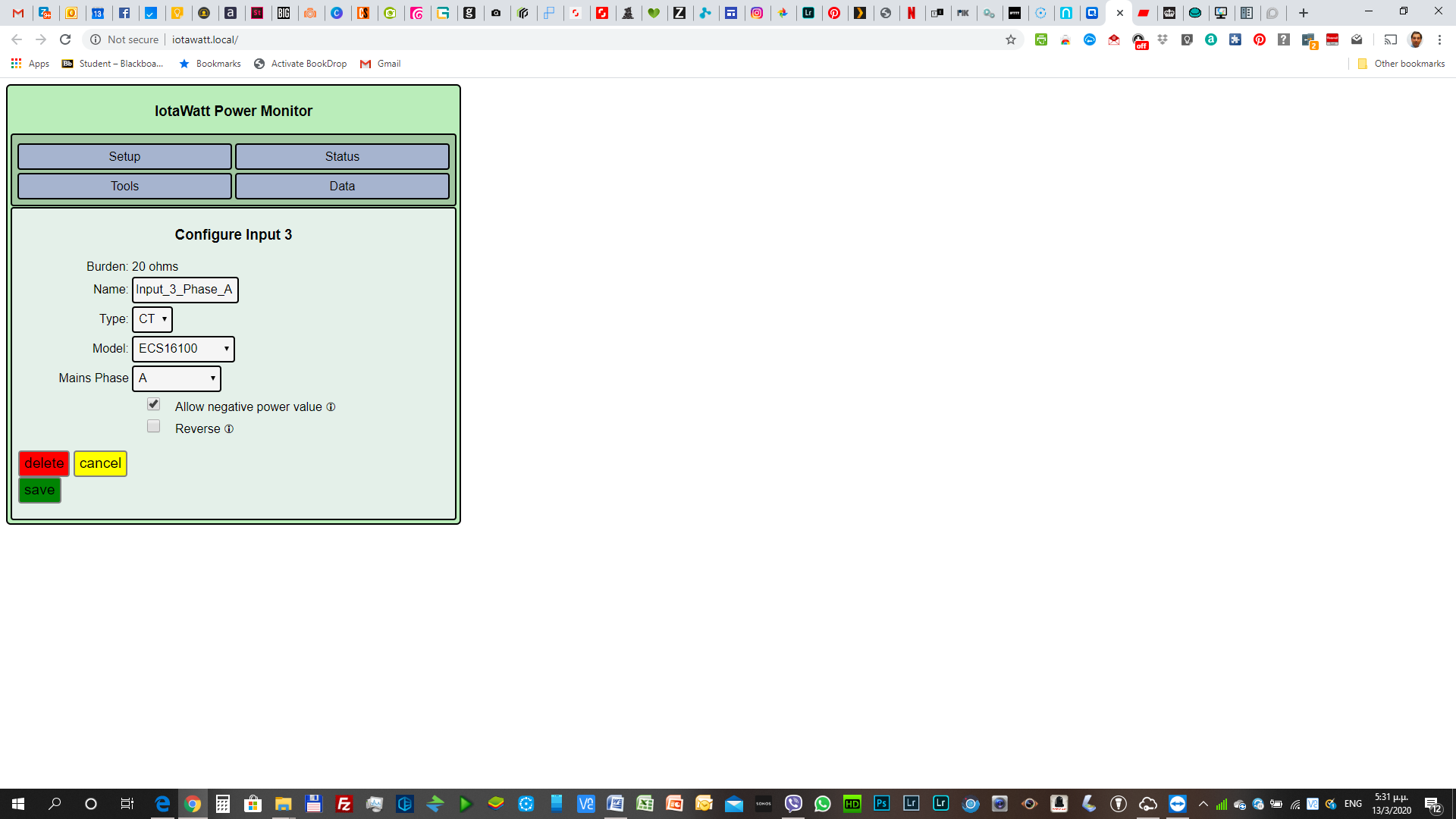
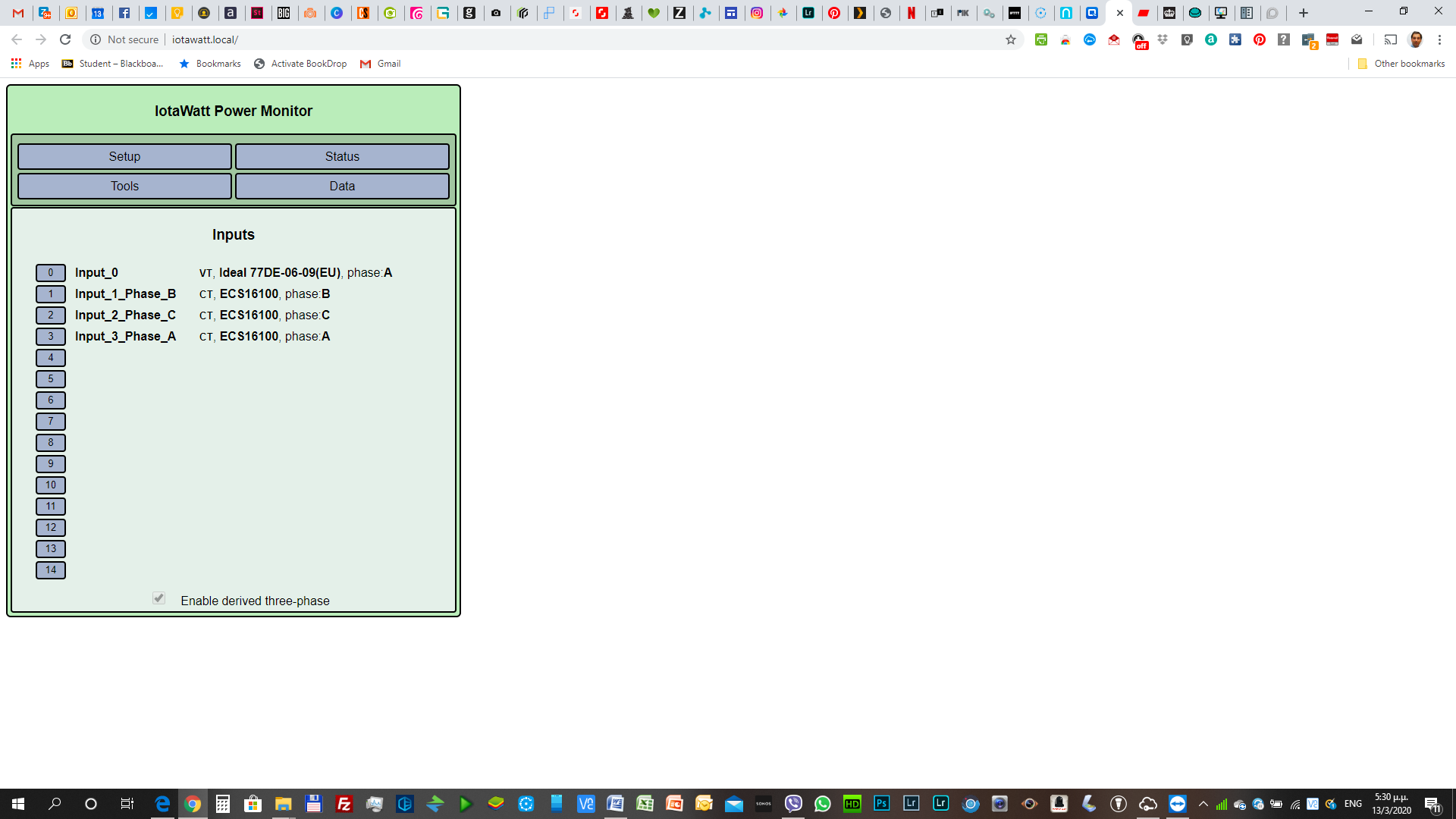
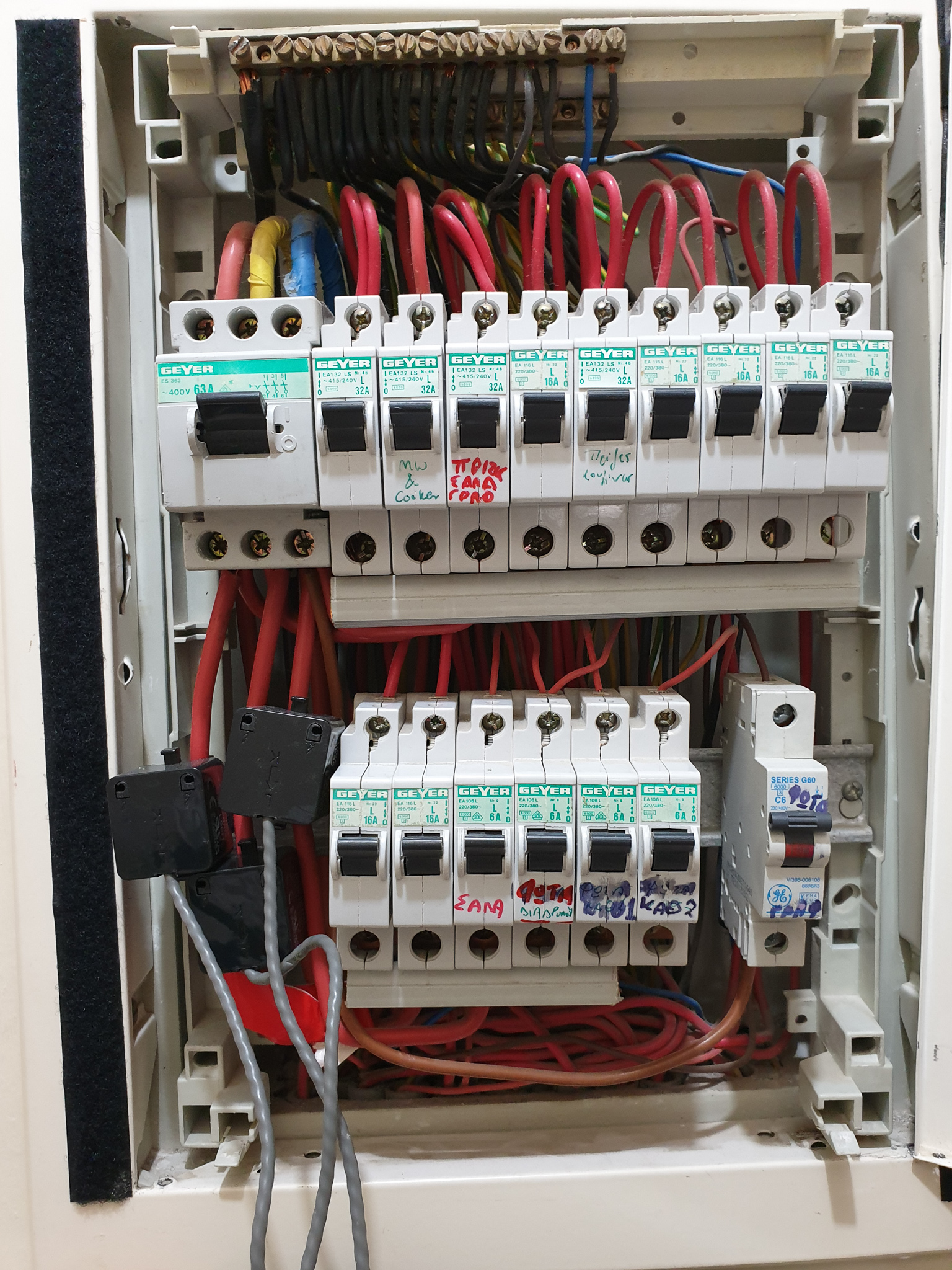
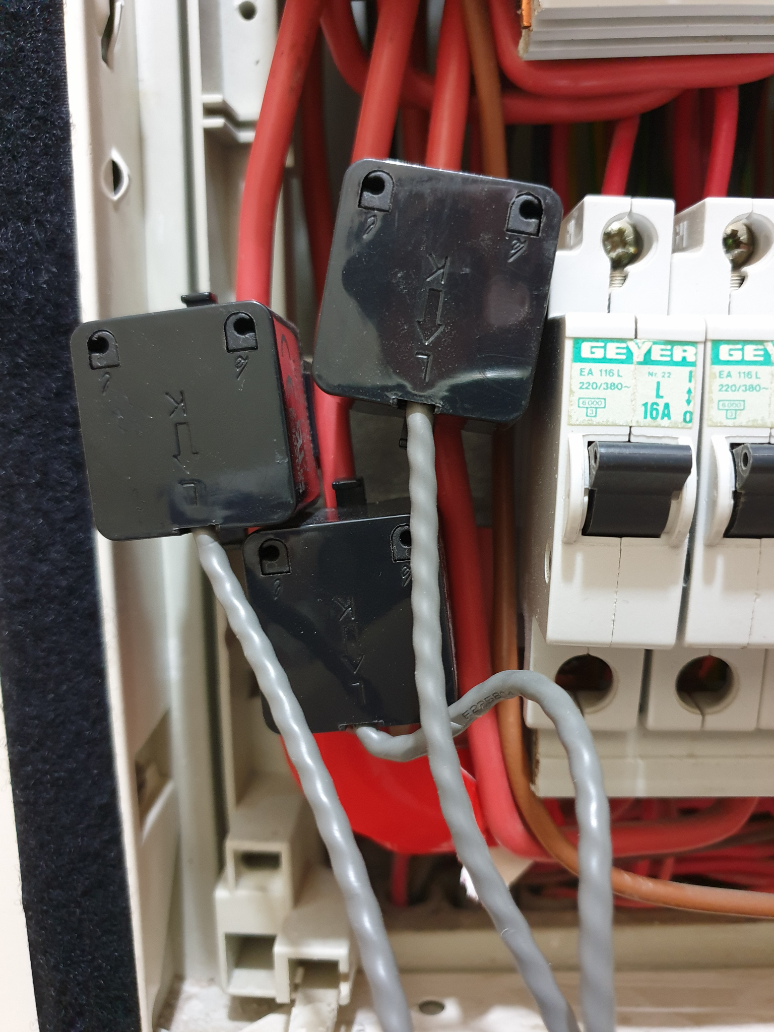
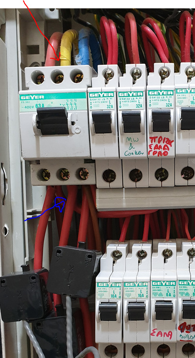
I have installed the IotaWatt system with three CTs aligned in the same direction on each of the three main live phases of my Electrical Panel Power supply at the three-phase Circuit Breaker distribution Board in my home’s domestic supply which is in Cyprus in Europe (240V to neutral per phase), similar to the UK electrical system. I have used a single VT and configured Derived Reference for the IotaWatt setup, hopefully correctly following the documented procedure. As an additional piece of information, my home installation uses also a net-metering photovoltaic system which I believe connects to one of the feeding phases via the relevant net-metering switching and measuring equipment.
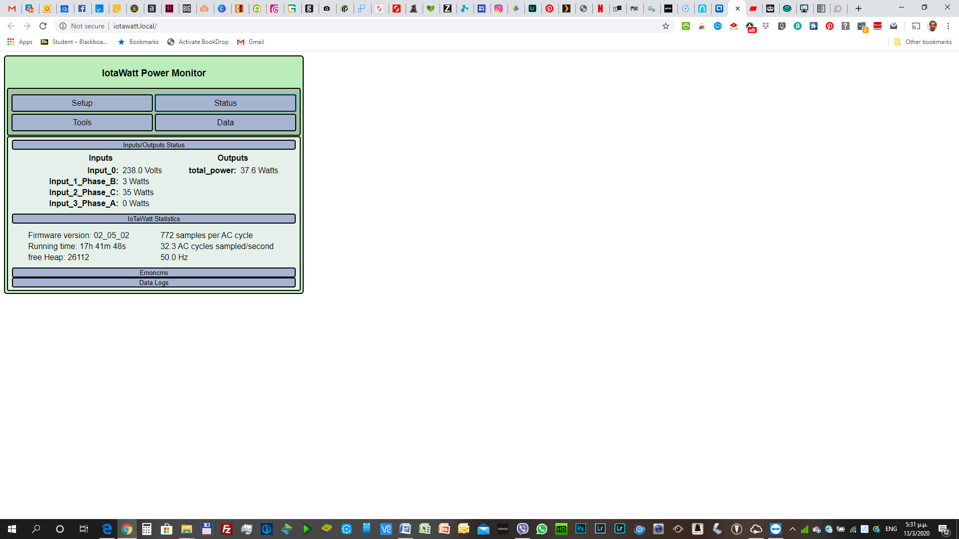
I have been able to measure correctly the power used by three different devices of known consumption connected on three separate phases as indicated by each of my three CTs (each connected to a different main feeding phase). However, I am facing a very strange problem. At any point in time, my total consumption is less than the actual power used, and a number of my home electrical and electronic devices connected to various outlets leading up to one or the other of the three feeding phases where the CTs are located, do not seem to trigger a reading on any of the three CTs when I switch them on. The above observations hold true both during daytime and at night when my photovoltaic system does not produce any power.
I am really baffled by the above. Can anyone help?