I have setup my IoTaWatt and am having some strange discrepancy with the readings…
I am only using the ECS1050’s and ECS16100’s that came with it.
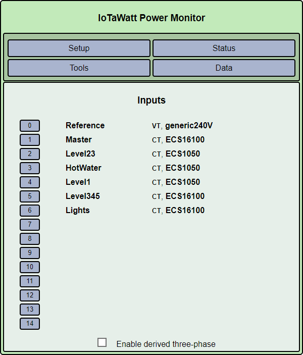
I have a ECS16100 around my (Master) input…
Then my 5 breakers (Level23, HotWater, Level1, Level345, Lights)
Total is an output of the 5 breakers
Reference:
244.0 Volts
Master:
480 Watts, pf: 0.90
Level23:
154 Watts, pf: 0.72
HotWater:
0 Watts
Level1:
245 Watts, pf: 0.73
Level345:
169 Watts, pf: 0.64
Lights:
0 Watts
Total:
568.2 Watts
… Shouldn’t Total = the Master?? (or be close to it)
Any ideas?
I am traveling to work atm… but will post a screenshot of the config screen when I get to work…
I have just selected the devices… they three options are not ticked (reverse, double, and the other one (I forgot what it is))
First, there’s no way the IoTaWatt is off that much. This is a configuration issue.
I can see this is going to take a long time, so in the interest of quicker resolution, I’ll combine a few steps.
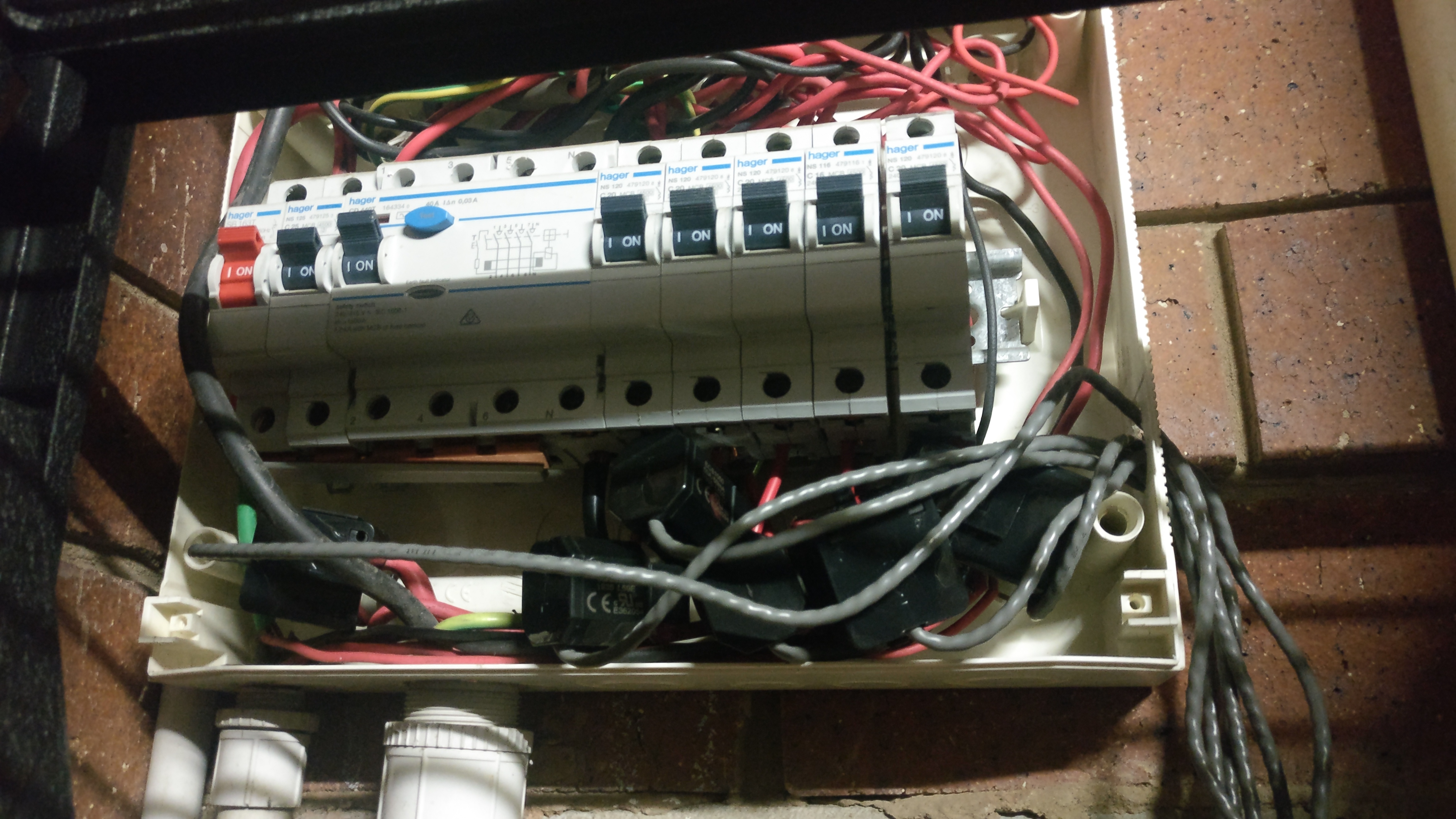
The picture doesn’t do me much good as far as determining what’s what. It’s a rat’s nest. I do have some questions:
There are seven breakers in addition to the main, which you say is the red one on the left. You are monitoring five. What is going on with the other two? I can see that one is the three-phase breaker that appears to have only a neutral wire running through it. Why is that on? If that neutral were carrying current, I would expect the breaker to trip on a ground fault. What’s going on with the one next to the main? It has a fat red wire that doesn’t seem to be part of the regular picture. I realize any power they would draw would make spread worse, but knowing them could also make the problem obvious. Can you show a screenshot of the status display with the unmeasured breakers off?
Is there any PV here?
It looks like the mains power, neutral and ground come out of the larger conduit on the lower left. The red appears to go into the top of the main breaker. The common and neutral go off frame at the top, presumably to some type of distribution block where all of the neutrals are combined, except for the black that still runs through the three-phase breaker. I’m thinking there is some kind of buss that feeds into the bottom of the load CBs. Some appear to have red wires feeding from someplace, and that’s where you have the CTs. If that’s the case, why not put the CTs on the top conductors as they exit the CBs? It looks like there’s more room up there.
Can you label the eight CBs, left to right?
Are you sure that the inputs have the correct model CT configured? For instance, if the Level345 CT is actually an ECS1050, then the power of that input would be half, or 84 Watts in your initial reckoning. That would add up to 483 Watts with a main of 480 Watts. That would mean the Hot Water would probably be an ECS16100.
Lastly, if you are really confident the configuration is correct, you take one CT off and clamp it around the same conductor os each of the others in turn and see if they are the same. This would be especially telling with the main, since that is alleged to be low.