Could you plug the hair dryer into the same outlet as the VT and see how the mains change. It’s important to determine that.
Are are 2 screen shots.
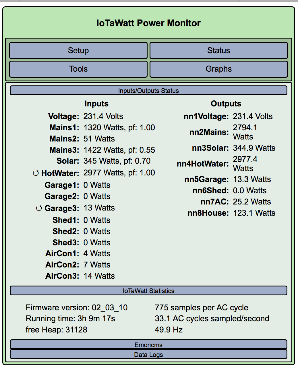
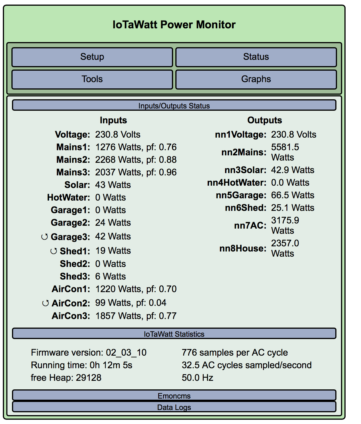
Hair Dryer ON
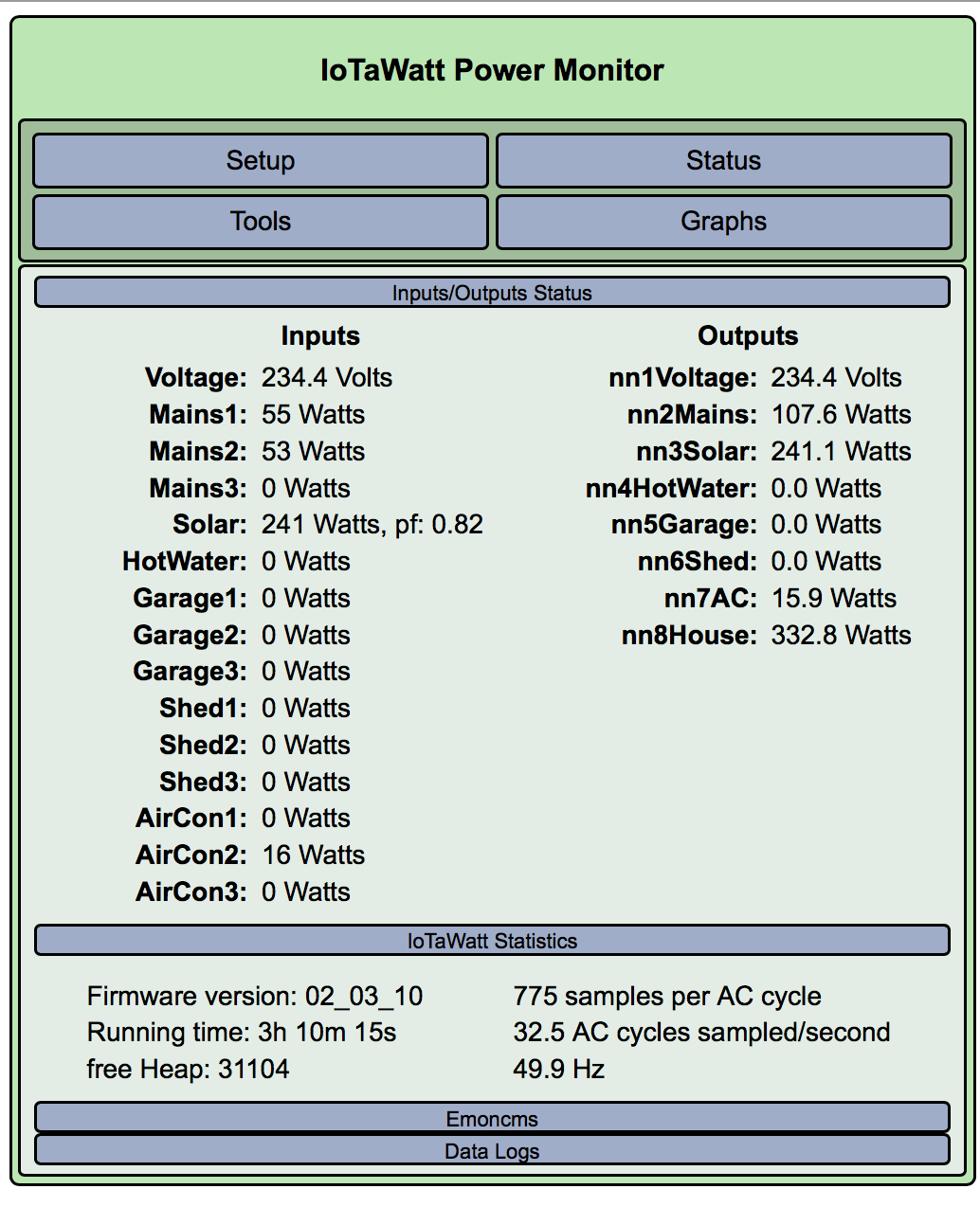
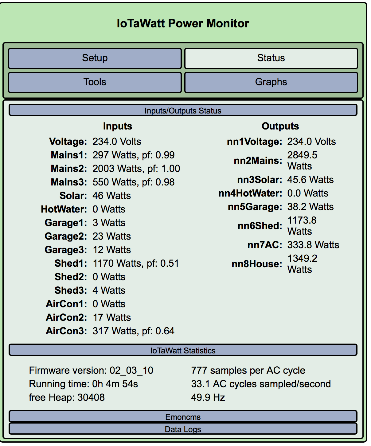
Hair Dryer OFF
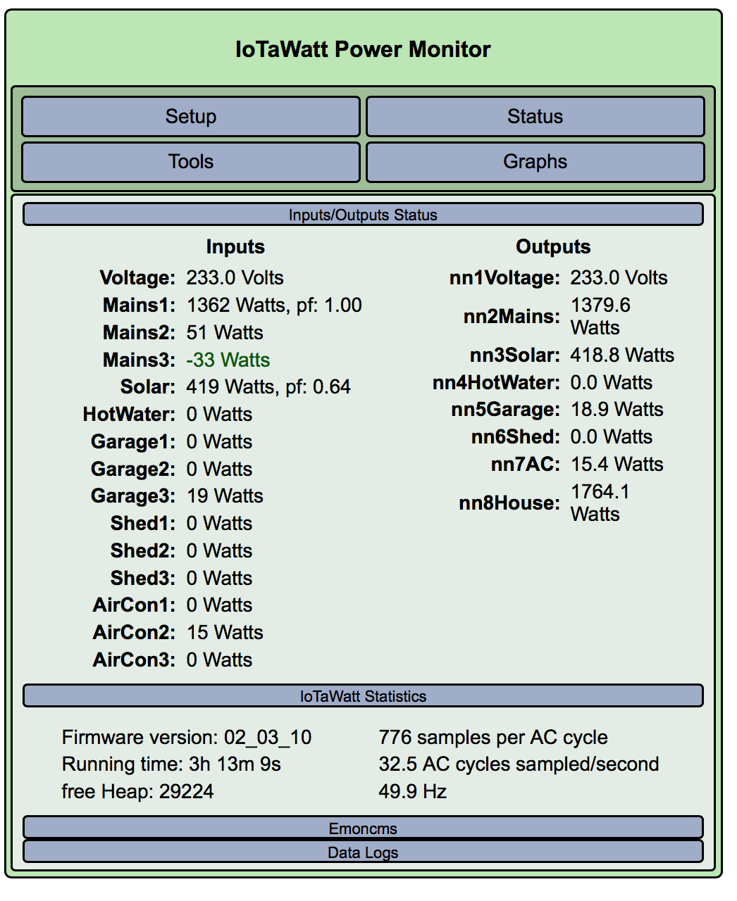
Hair Dryer ON (With no Hotwater)
EDIT
Added Hair Dryer ON with no Hotwater ON as I realised it may affect trouble shooting
Hair Dryer is labelled as 1800watts but…
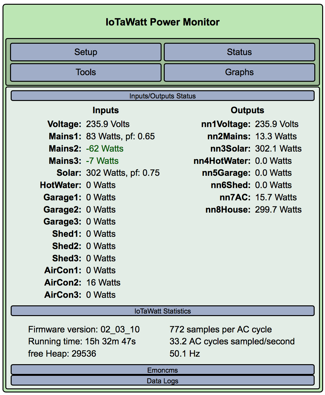
It looks as if the VT is on phase A. Not sure about the 1800 watts vs ~1300, but pf 1.00 indicates the correct phase.
Im curious why the hot water is now 3000watts with pf 1.00. Did you change that to phase B?
I agree that VT is on Phase A.
I changed Hot Water to Phase B as when it kicked in, Mains B spiked in conjunction so I made assumption it was B.
Let me know what you want me to do next.
I will get you photos of the boards I am dealing with tomorrow when I have some light.
One has been updated a little and 2 are pretty old.
It does appear to be on B. From the previous experiment it also seems to be on main3, so I think main3 should also be phase B and by elimination, main2 should probably be phase C.
With the mains properly labeled, you may be able to determine which main is associated with each of the remaining circuits, and assign them to the same phase as their associated main. This is where you may find that the various feeds to shed, garage, and AC are color coded by phase.
Of particular interest will be the solar, because the main associated with that should have “allow negative values” checked so that it can properly track exported power.
For the benefit of anyone reading this to understand the logic, I misspoke here. What I meant to say was that it looks like the VT is on main1.
With this derived reference method, the VT is always on phase A by definition. That is to say that the definition of phase A is the phase where the VT is located.
The phases had been assigned to the mains somewhat arbitrarily as a starting point, and as it happens, main1 was assigned phase A and the plug for the VT is on the main1 circuit.
Note that main2 and main3 were also arbitrarily assigned to phases B and C respectively, but those turned out to be incorrect and it was actually C and B respectively.
The notion of numbered circuits 1, 2, 3 and phases labeled A, B, and C are arbitrary labels, and does not necessarily indicate any ordinal relationship between circuit and phase. That must be determined by observation, or tracing circuits, or some other method of deduction.
Once determined, it is possible to sort it out and establish that ordinal relationship by moving the CTs. In this case that would involve swapping the CTs in inputs 2 and 3, and reassigning the phases 2=B, 3=C.
Or not, you can just leave it as it is recognizing that phase is just a new attribute of the circuit and doesn’t need to have any ordinal relationship to the names.
I have updated Main3 to Phase B and Main2 to Phase C as suggested. This then gave me the following results which may mean I need to reverse the CTs?

Solar was already set to allow negative and we have some sun so we should be able to get some readings soon. (Picture below of Solar generation as of 9.44 this morning. I think there is something else I need to tweak with solar as it thinks I am making 44 watts or so during the night so I think it might be reading a little high at present)
I will post some pictures of the board as I am assuming that
With the mains properly labeled
you mean with the configuration we have done vs any clues left by the installing electrician???
UPDATE: Added a picture with some solar happening
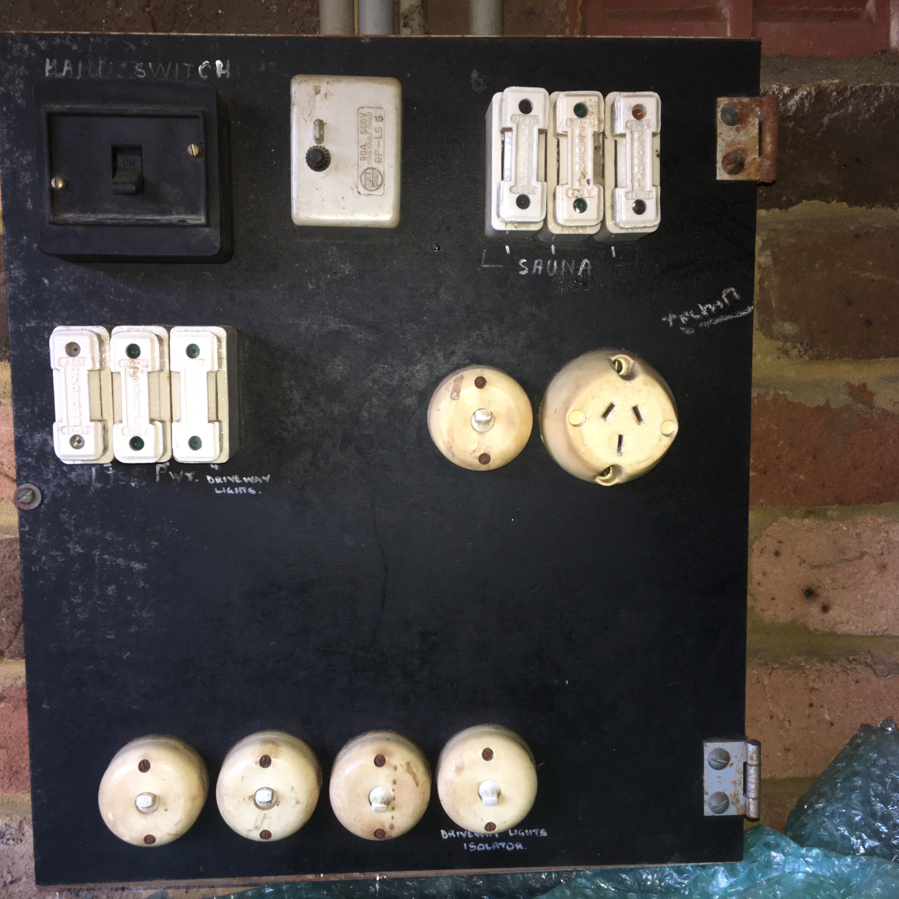
Here are some photos of the electrical boards I have inherited on this property. Once I get a handle on things and some spare cash, I may upgrade but at present its a low priority due to cost.
Originally built in 1974? and the Garage and Shed boards are still original.
I believe that the solar was installed in 2007 and included a refresh to the main board.
The wiring is still pretty much original behind the boards. (eg red/black/green which is old for australia and no color coding for the phases).
CTs are all installed behind the main board which hinges and is an external metal box (typical for Australian)
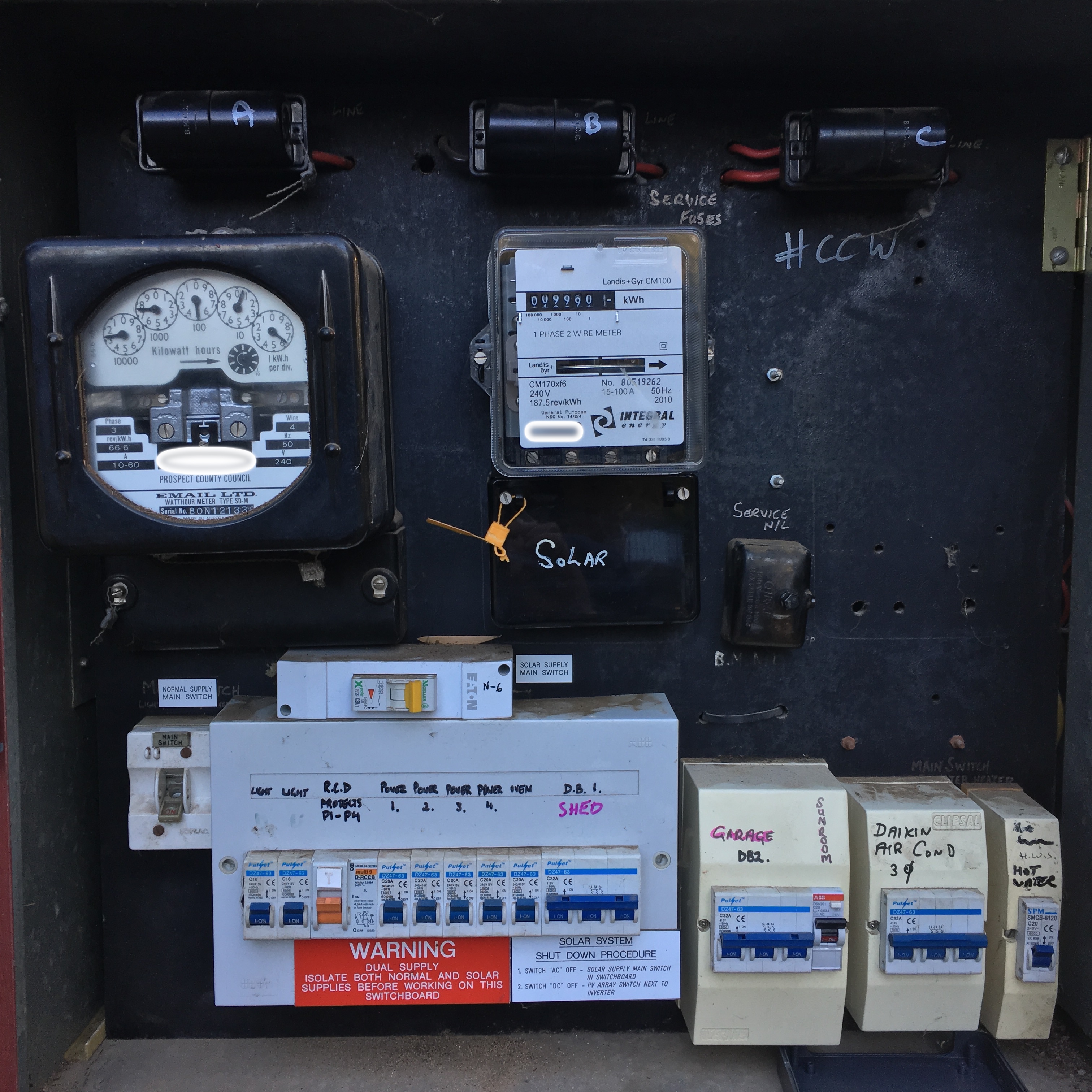
Main Board
Garage
(workshop power/lights/sauna/fridges/etc)
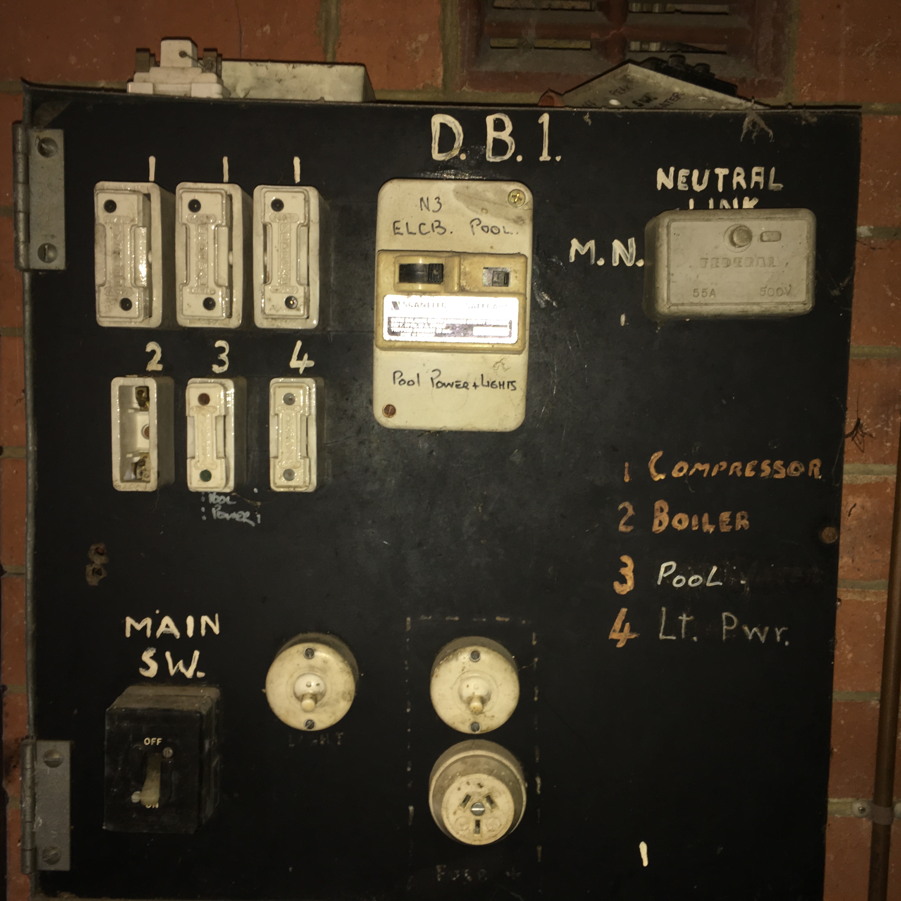
Shed
(only the pool is connected these days - no boiler/compressor)
That equipment is completely foreign to me. The interconnecting wires are not visible and I can’t see where any of the CTs are placed. Not looking for more pictures, just saying I don’t think that will help.
What does seem to be useful is the newer breakers for garage, ac, shed and hw. I don’t see any reason why those should not be wired the same left to right, so if the CTs on those are in order, the phases should correspond the same.
That said, I don’t think we have the mains right yet. The CTs on those incoming cables should all be oriented the same way. Is that the case? I’m thinking it could be that main3 is phase C, and the CT is reversed. There are a lot of combinations of phase and CT orientation, and the effects of erroneous combinations can be similar.
So can you check the orientation of those CTs?
If I were there on the ground, I could probably figure it out in an hour. Halfway around the world, might take a week.
All good and I can get you photos of CTs if you want but I don’t think it will help. Just a matter of slow and steady trouble shooting.
I have checked the Phase 3 Main CTs.
Phase A and Phase C have the CTs in the same orientation.
Phase B has the CT in reverse.
I assume I should change Phase B to be the same as the A and C
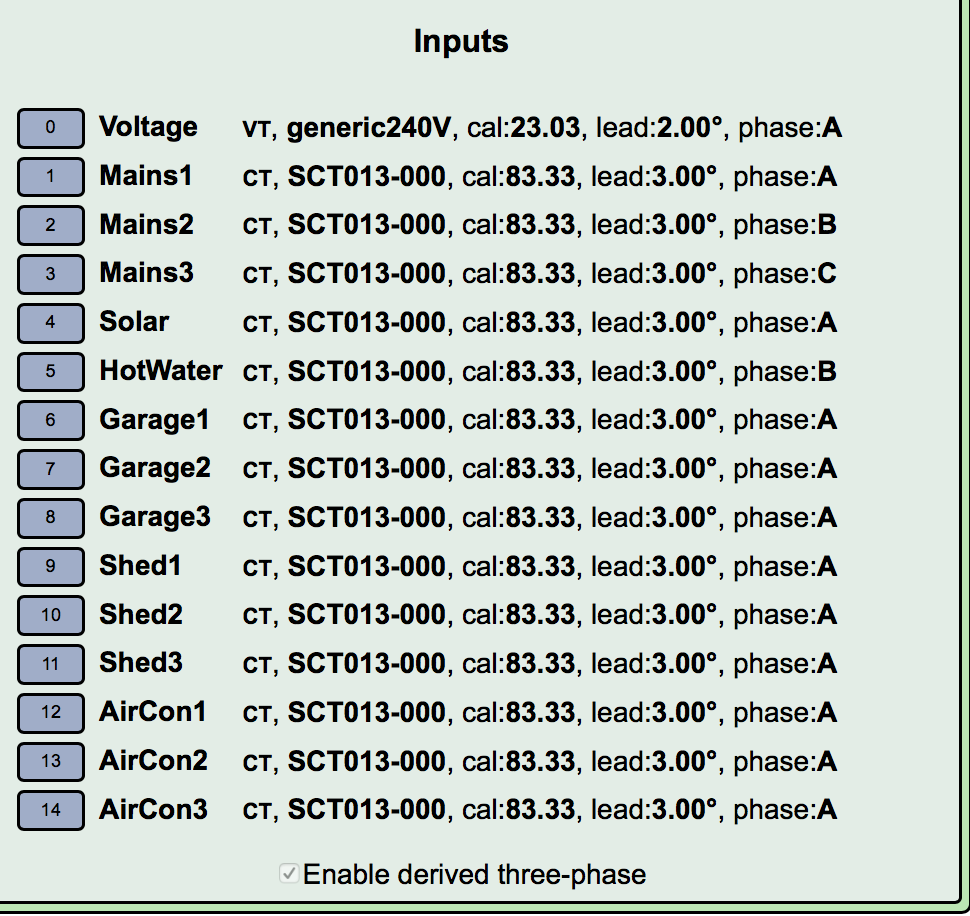
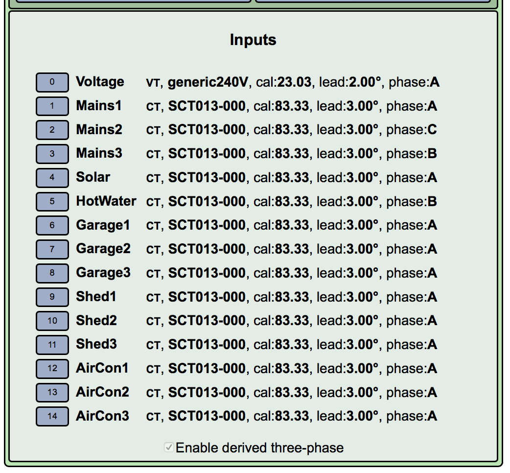
As I understand it, the assignments are currently:
Main1: phase A
Main2; phase C
Main3: phase B
Just to be clear, are you saying that the CT on main3 appears to be oriented differently from the those on main1 and main2?
On the inputs to the board
Input 1 assigned to Phase A
Input 2 assigned to Phase C
Input 3 assigned to Phase B
CT for Input2 is reversed when compared to the other inputs.
Will post a photo.
If it helps for trouble shooting we can plug / unplug whatever you need to determine stuff
Front (Left to Right: Phase A Phase B Phase C)
Rear (Right to Left: Phase A Phase B Phase C)
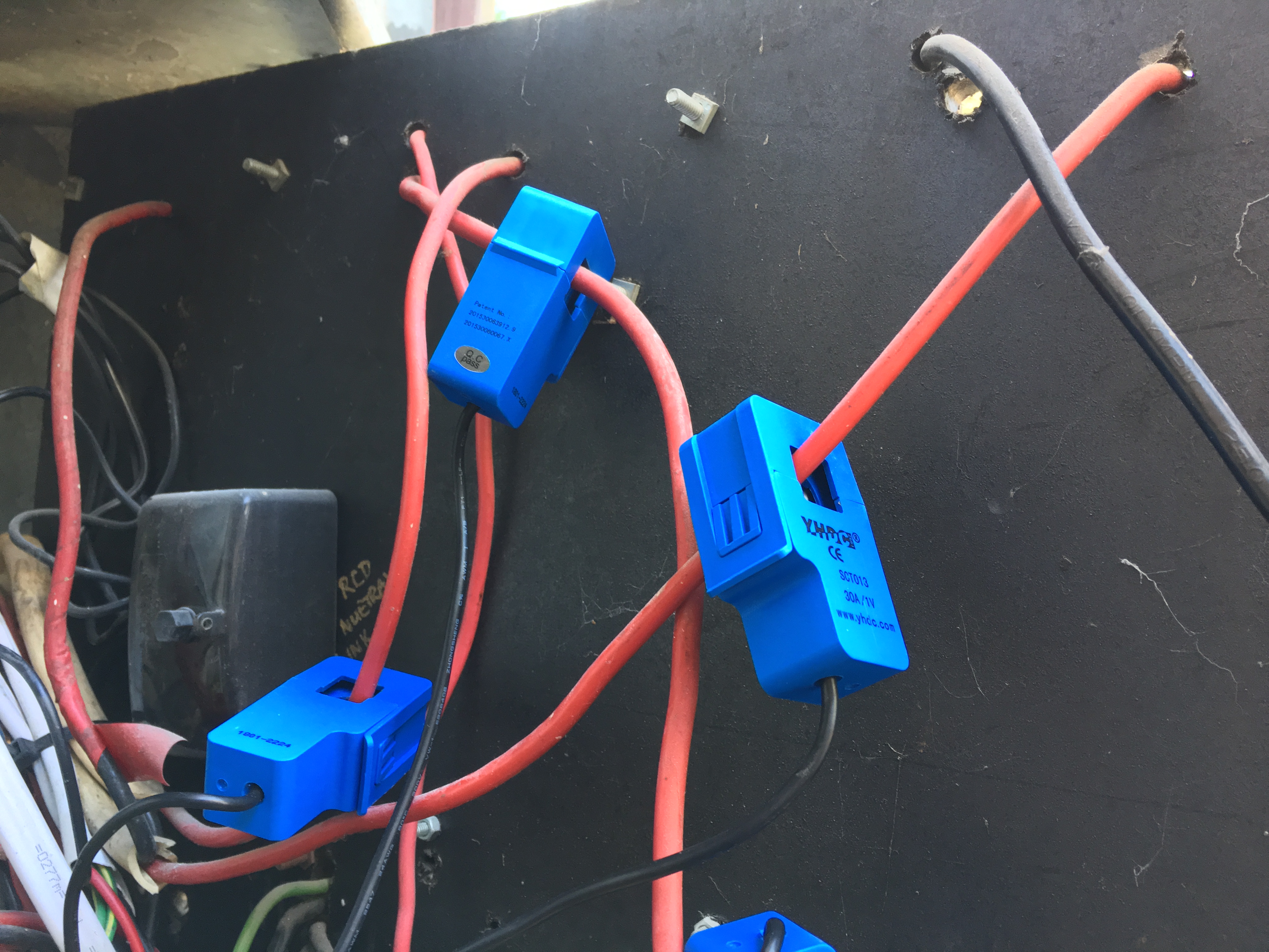
(Note that the CT for Phase B is actually on the far left and as you can see its backwards compared to the other 2)
Can’t really see the full picture. Those big fuses have two leads, but it’s not clear which are connected to the supply, and which go to the load. Can you verify that all of the CTs are clamped to the supply, or all are clamped to the load? Because they go one way on the supply side and the other on the load side. The current flows into the hole for the supply, and out of the hole for the load.
Do you have a fire extinguisher?
We have a fire extinguisher.
I will swap the CT for Input2 which is currently mapped to Phase C
- it had been around the other way anyways originally and was only swapped as we saw negative… Our mistake. Will try and get a better shot but its tough as the board is mounted and swings and there isn’t much play…
So… Here is a screenshot from Status.
Unit is now running on Raspberry PI power supply. Plugged next to VT.
I have swapped polarity for CT for Input 2 (Mapped to Phase C)
I have moved CT for input 3. They are now all on the before side of the fuse whereas before Input3 was on post fuse compared to the other 2.
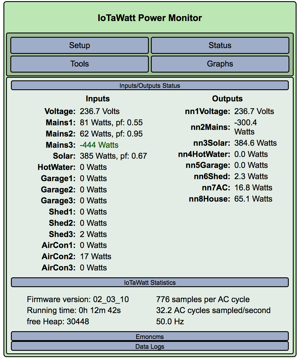
I am guessing next step is loading up something.
In the pictures above the fuses are marked ‘Line’ side on the right so that would be the supply side. On C phase the CT in this picture is on just one of the load conductors so not measuring all of C phase.
For simplicity it would be best to put all the CTs on the single line side conductor for each phase.
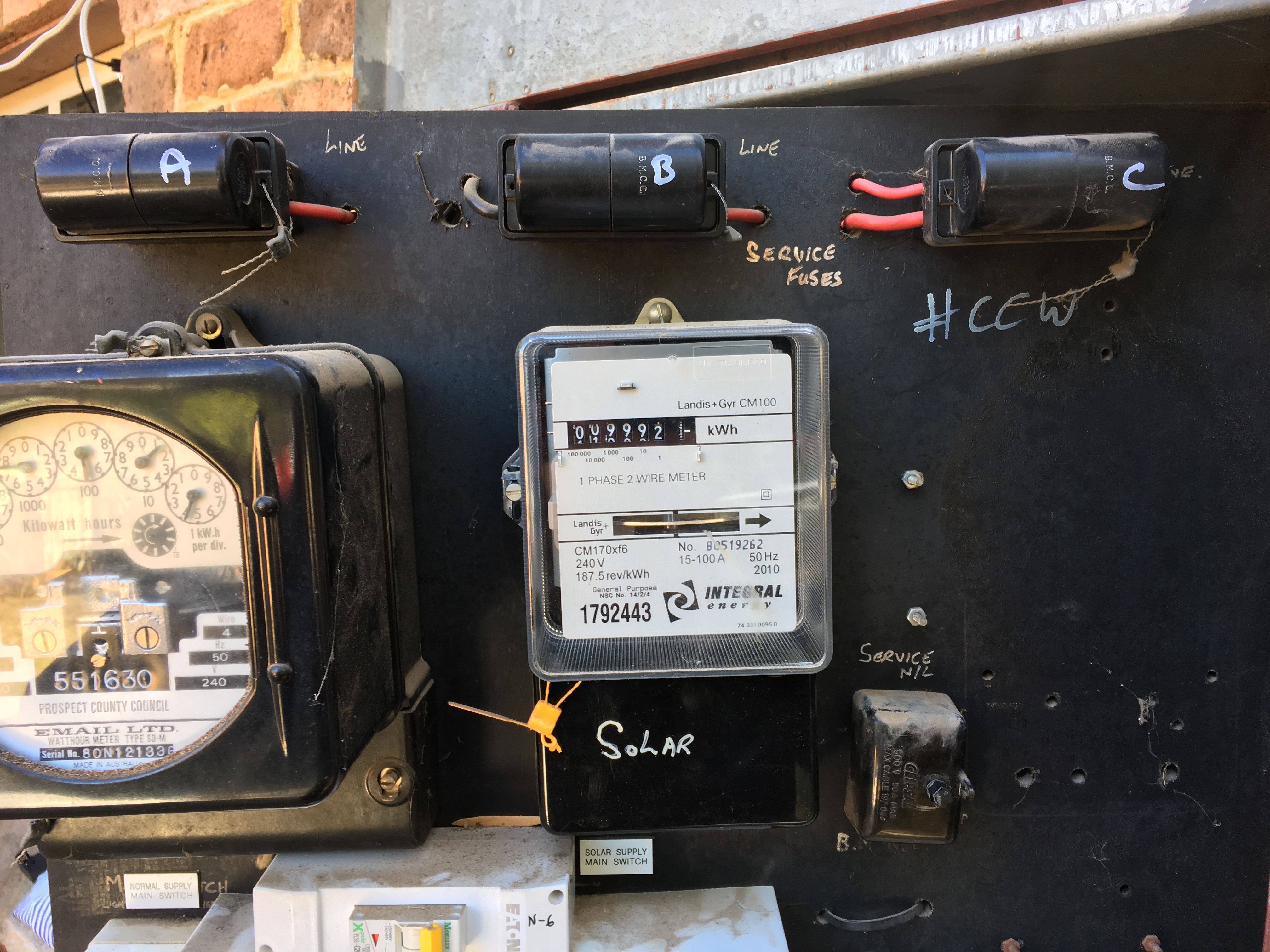
The way these boards is wired is that the supply conductor from the street is first connected to a service fuse that is then connected to a meter and then goes to sub circuits.
In this board there is an original 3 phase meter and when solar was added a single phase meter was added to measure total solar output (gross metering). You are losing a lot of money with a bigger bill by not switching to a net metering arrangement.
1 Like
Hi Pbraz,
I agree re the net metering - just moved in (a few days) and was trying to see how bad the AC was really hurting me.
I have moved the CTs to the single line conductor for each phase and its looking better (I think…) Just need to start getting the other outputs CTs assigned to the right phases.
That said, any advice is appreciated.
Current status (new Raspberry Power Supply and Unifi Wifi network)
And with the AirCon fired up. Something still needs tweaking in phase assignment.
Thanks for looking at this Paul. It’s good to have someone familiar with the local equipment and methods. That explains something I could not reconcile from earlier on. I had pretty definitely determined that the hot water was on main3, yet the total power of main3 was less than the power to the heater.
Still not convinced the mains are assigned to the correct phase, but it does look good.
@bluetardis, do you have an AC voltmeter? If so, you could use it to associate other circuits to the mains. Voltage between phase corresponding circuits will be near zero, while between different phases will be close to 400 volts. Be careful though.