I am just getting started with IotaWatt and have a question. I have SunPower Solar and am trying to monitor the output from the solar feeds. The cable comes from the Solar breaker box and then goes into my main breaker panel, where they are spliced into the main feed from the utility. I’ve placed the CTs in the Solar panel and then tried the main panel (using the feed lines from the solar panel). The system shows 400 watts of general on each leg at night when there is no sun. I would assume it should be 0 watts. I am using the AccuCT 50A x 10mm split-core CTs. The solar system is rated at 13Kw total. Does anyone have any ideas on what I should check? For what it’s worth, the mains and another set of CTs monitoring an AC system seem to be reading correctly.
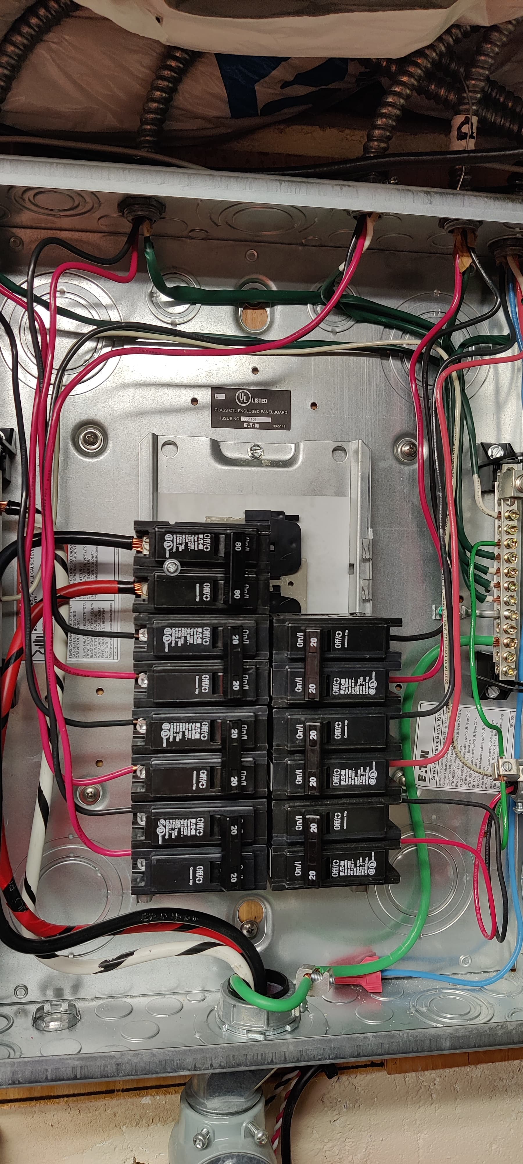
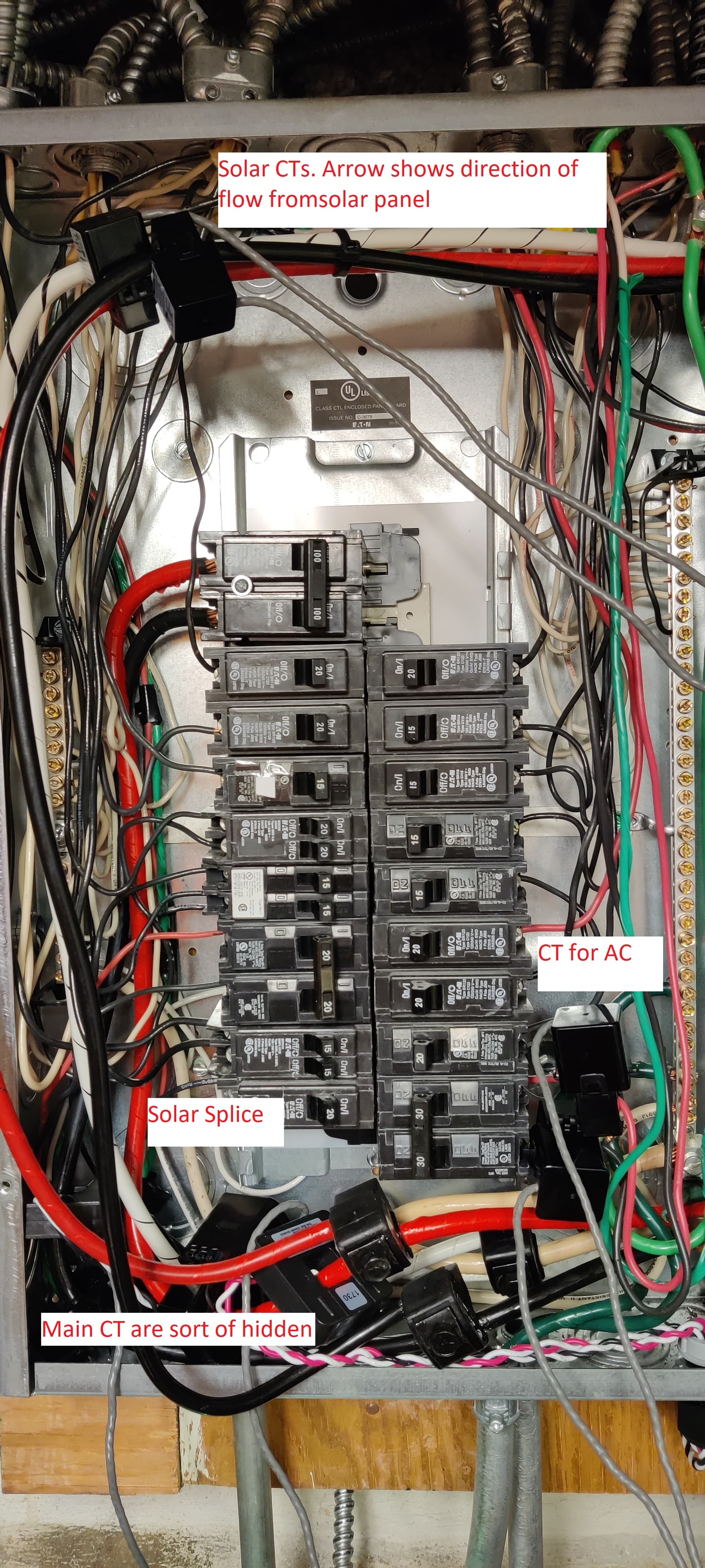
Can you post good resolution pictures of the panels please and a screenshot of your status and inputs setup?
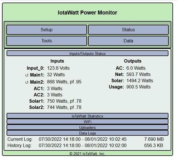
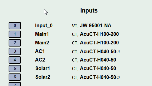
Forgot the inputs
Looking at your solar feeds panel, it appears there are six potential solar feeds (micro-inverter strings?), but one of them is not like the others. While five of them are two-wire (the third wire is ground), the sixth in the lower right is three-wire. I suspect that is some kind of load and probably drawing the 400W.
Try turning that off tonight and see if the panel goes to near zero (micro-inverters can draw some minor stay-alive power).
Moving to your main panel, you should be aware that the solar is connected upstream of the mains CTs. The typical install is downstream. It will work fine, but the mains will not go negative on export. Your usage (excluding that 400W load in the solar panel) will simply be your main, as if you have no solar. inport(+) and export(-) will be:
Main1 + Main2 - Solar1 - Solar2
OK. So turning off the solar panel does help. When I turned it off the watts for solar went to 0, as it should. I don’t know enough about how the panels, invertors, or supervisor works but it appears to use power when it’s dark. I will speak to the solar company about that. Wish me luck.
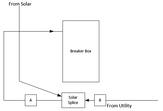
As for where to put the main CTs, I have them between the main circuit breakers and the solar tap, which would be A in the diagram I made. Are you saying I should have them attached at point B?
And thank you for the help!
The experiment was not to turn off the whole panel (the 80A breaker), but to turn off only the 20A breaker on the lower right. Is that breaker labeled on the cover plate?. That breaker appears to be different from the other five.
Everything appears to be copacetic, so I doubt the solar company can be faulted. It’s just that there appears to be a load serviced from that panel in addition to the five PV feeds.
I’m saying the most common convention is to have them at point B. It will work fine at point A but most of the examples of how to configure things are for the more common convention.