I just got my IoTaWatt device and have connected it to some SCT013-000.
I have also installed emoncms and linked the IoTaWatt with this.
The problem I have is that on the status page of the IoTaWatt it show too low Wattage, I put on 2200W load and it only shows 1100W.
I use an oven and confirms the load with an old watt-meter I have in my house.
I have calibrated the AC-AC adapter so it shows the correct value.
I have tried to edit the config.txt and tables.txt “cal” value, but nothing makes a difference. (After a restart of the IoTaWatt)
I have seen that I can multiply the input from the IoTaWatt in emoncms to get a close to accurate measurement.
But what is the recommended way to do this?
It does sound like a configuration issue. I don’t recommend that you edit the config.txt file directly as a syntactical Json error will cause your device to not boot. You should be able to do everything through the configuration app.
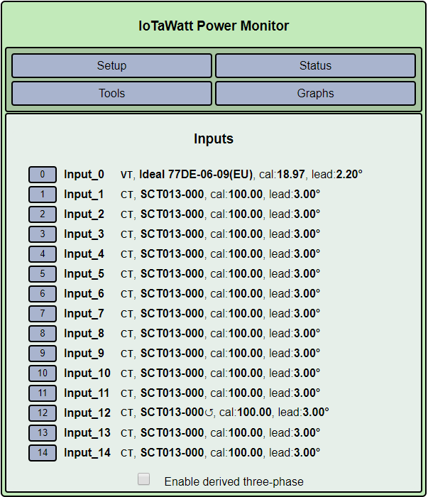
To address the problem, could you tell me what kind of power system you have (country, voltage, frequency) and could you post a screenshot of your input configuration as well as a screenshot of the detailed configuration of the oven in question?
OK, so you have three-phase. I understand that you believe everything is on one phase, but being on a different phase from the voltage transformer for a resistive load like a range will produce exactly the result you are seeing.
So humor me. in the configure inputs display, check the box at the bottom that says “Enable derived three-phase”. The display will change and each input will now be assigned to phase A.
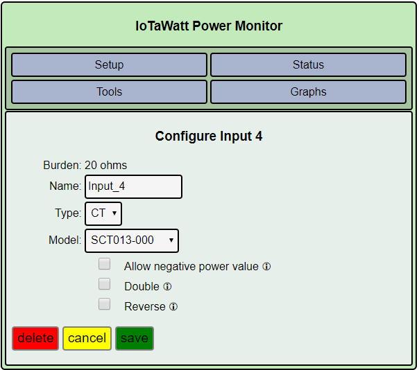
Now edit input 4 and change the phase to B. Then try running the range. If the result is the same repeat using phase C.
That should only take a few minutes, come back with the results.
Right. To get real power, it has to consider the phase relationship of voltage to current. That is the primary reason for the derived reference phase assignments. If it were only voltage, you could just plug in 230V, do without the VT, and get decent results to the extent that your voltage is close to 230V.
So a good result on phase C indicates that your range circuit lags the VT circuit by 240° (or leads it by 120° depending on your point of view). If all of your loads are on the same phase, and I’d double check that, you should probably move the VT to that phase and change the range back to A. Whatever phase has the most important loads should be phase A as that phase has the absolute correct voltage. Certainly if you have a single phase PV inverter, tha VT should be on the same phase as that.
You have the tools there to get everything right, it will just take a bit of work to configure it.
I checked my fuse-box and it looks like they have tried to divide the circuit breakers evenly among the phases. But I will test more to see what phase has the most load.
What about when the current max load moves from a phase to another?
For example, normally the heating in my house uses most power. But during dinner time the oven uses most power.
Is the “absolute correct voltage” differentiating that much on different load? (I checked now and all the phases has the same voltage ±1%)
Absolutely, I will have to document and find what phase is on the VT and on each CT and configure it correctly.
It offers some methodology for setting up three-phase. It’s important to be sure all of the CTs are oriented the same way with respect to the mains and loads, otherwise it becomes nearly impossible to sort out. You can reverse them physically if they are easy to get at, or you can do it virtually in the input configuration. I saw that you had virtually reversed input_12 and that was a clue to me that you might have three phase.
Don’t worry too much about which phase is dominant at any time. Get the mains right first and then move on to the individual branches. If you have solar PV, I’d recommend making that phase A unless it’s the only thing on that phase.