Hello!
Yesterday I’ve recieved my long-awaited IotaWatt. The installation was pretty painless, despite the fact, that I live in Poland and have w 3 phase 4 wire system.
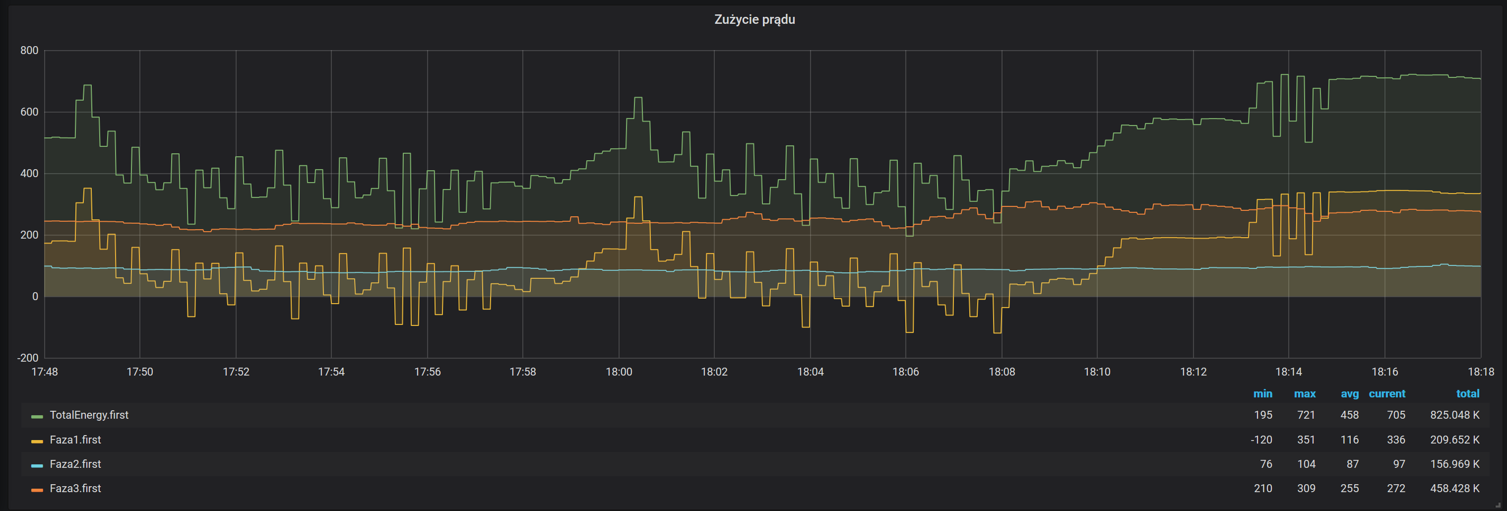
My first milestone is to have an accurate and reliable overall power meter. I’ve used the docs how to install on a 3 phase derived system: installed the voltage transformer and 3 CTs on all 3 phase power lines (black, grey and brown wire). I’ve just looked at the graphs, both in Grafana and in Graph+ and I can see, that one of my phases is giving negative results:
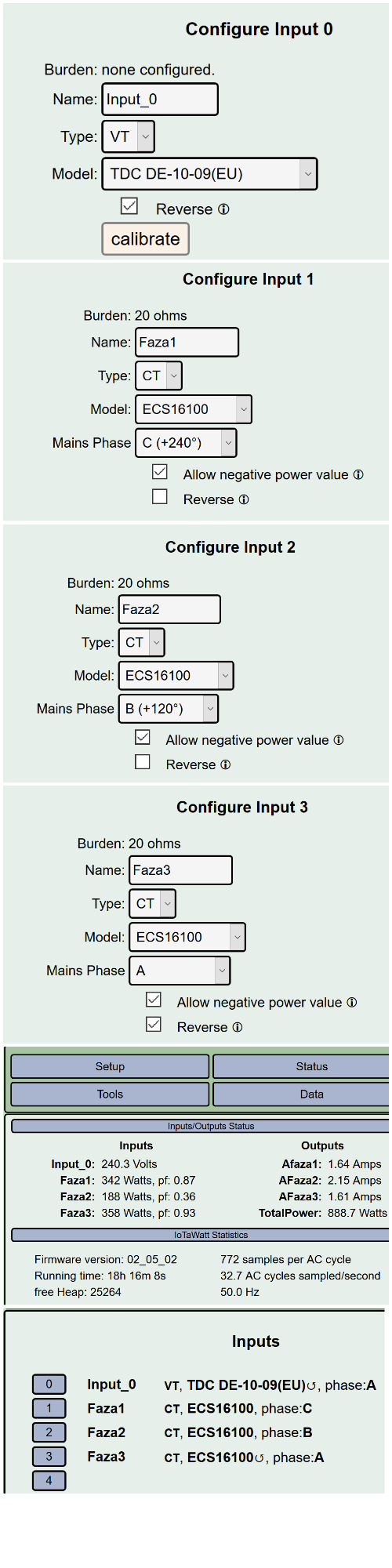
The reversed checkbox is checked on inputs which were identified by iotawatt as reversed (but that also changes in time, so I’m not sure is it done right).
Tomorrow I’ll check if CTs are mounted in the same direction, but I was under impression by one of the forum topics, that it can be corrected (even in 3phase system) programmatically.
So my question is really - is my set up ok, or are there any mistakes (negative output from one of the phases?)?
Update 1: I’ve set the wrong model for my VT (but I calibrated it manually).
There are 36 combinations of CT orientation and configuration. Only one is correct and will yield accurate results. Insuring that all of the CTs are oriented the same way with respect to source and load reduces those combinations to six. So make sure you have done that, and that the reversed checkbox is off for all three mains.
Next you must identify which main is the phase your VT is connected to. One method is to connect an appliance to the same circuit and cycle it on and off several times, then look at a plot of the main and see which one changes accordingly.
That is phase A. If the mains power for that phase is negative, reverse the VT, either turning it in it’s socket or checking the reverse box in the configuration. Once this is done, the remaining two mains are phase B and C,or C and B.One combination should result in about twice the power shown as the other.
Thank you very much for instructions. It turned out, that all the CTs were oriented the same way, I correctly identified phase A that my VT is connected to. The only mistake was to switch phase B and C - that’s why they were giving wrong results.
So far, so good. I’m going to monitor the system for a longer period of time and get back with results.