Made the switch to storing VA in the datalog instead of pf. Since then, everything has fallen into place. I’ve got a branch working where you can specify units of Amps, VA, pf, Hz, Watts, Volts, kW, kWh and that’s what comes out of the calculator. The values can be used to upload to Emoncms or influxDB or plotted in the local graph. The averages are accurate over any time interval.
The algorithm allows adding and subtracting inputs as before, so if you wanted to know the power factor of your mains with the air-conditioner off, you can subtract the AC from the main in calculator and get the resultant pf. Same with Amps and the others.
Only downside now is that my year old datalog doesn’t have the VA so I can’t look back on it.
If the Iotawatt can produce kWh and log to the SD card and log to influxDB that would be a great feature.
I have been using a continuous query in influxDB with the integral function to produce kWh but would prefer not to do this. I also use Grafana for graphing as it is powerful and looks good.
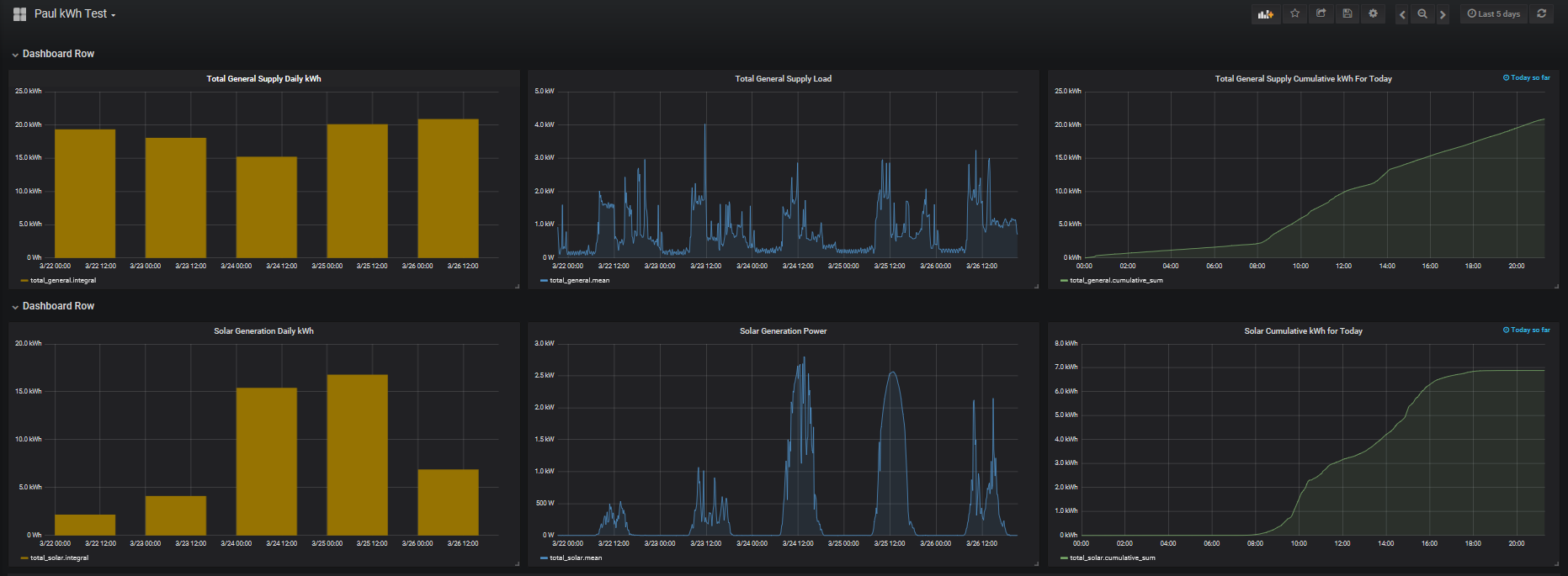
One thing I would like to do is show a cumulative kWh graph for example as consumption (or generation) grows during the day but to this then needs to reset at the start of the next day. I can’t see how to do this with influx or Grafana, trying to learn kapacitor as it should be capable but the scripting language is a bit obscure.
PVoutput has good standard graphs for a growing cumulative kWh graph as below.
@Giraffe, I use the following query to generate a cumulative kWh graph. The 2380 is an offset to sync up with my electricity meter:
SELECT cumulative_sum(integral("value",1000h)) + 2380 FROM "house_power" WHERE $timeFilter GROUP BY time($__interval) fill(null)
@overeasy, I think the ability to select units is a great addition and looking forward to trying it out! Only suggestion would be to have a mechanism to “sync” the kWh field with the electricity meter reading when required (e.g. on initial installation of the iotawatt or if you get a new electricity meter). Perhaps, allowing to overwrite the last kWh value via the iotawatt UI and have it continue to aggregate and publish from that value onward would work?
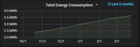
As a side note, the drift against meter has only been around 0.4% over the last 6 months which is pretty good in my book!
Awesome! That’s well under the 1% of a typical revenue grade meter. My question is which is the more accurate, the IoTaWatt or the Meter?
Overnight my bench system has been recording the newly added VA in the datalog and I took a look at a couple of these new outputs:
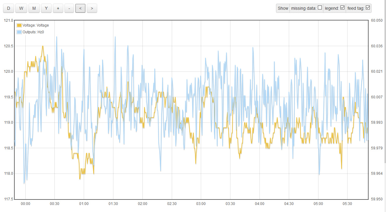
Here’s a plot of frequency vs voltage. Trystan Lea at OEM had pointed me at a UK website some time back that showed how frequency was related to load there. I think I see something similar here.
I know it looks like a mess, but keep in mind that the range of voltage covers about 2 volts and the range of frequency is about .04 Hz (0.07%). Nevertheless, if you squint a little, the larger voltage swings seem to correlate with frequency.
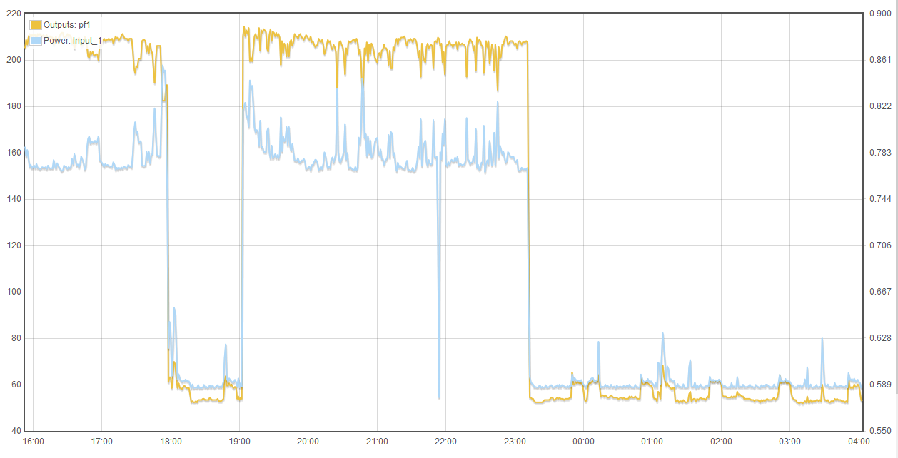
Here’s power factor. For convenience, I keep the bench test system monitoring my desktop computer with a couple of solid core CTs. I’ve seen the pf go up and down in real-time, but this just puts it in perspective:
Not sure that frequency would vary with load due to anything happening at a local level.
At a whole of network level (eg country or state wide) the frequency is will change where there is a sudden significant mismatch between generation and load that is not immediately compensated for.
Locally the voltage would drop as load increases and visa versa due to the source impedance of the network at your particular location.
A falling (or climbing) frequency outside of system stability design is a scary thing for a network operator - means there is going to be a blackout that affects all or large parts of the country.
This doesn’t work for power factor. It has been enlightening for me to try it and figure that out. The PF using recorded va works fine for one ct, but you can’t do math on it. The result appears to be meaningless. I think I undestand why but will leave it to a power engineer to explain it in proper terminology.
Just trying to help but from memory this might help. Happy for anyone to jump in and correct if I am wrong.
VA and Amps are vector quantities so you can not add them together (linearly) if they are not in phase but must use vector addition. If the circuits have a different power factor then VA and Amps will not be in phase for the different circuits. Power factor can then be calculated from the vector sum of the two loads.
For example
Circuit 1
VA = 100
Watts=90
so can calculate pf = 0.9 and Var=43.59 (VA is hypotenuse and Watts and Var are other sides of right angle power triangle)
Circuit 2
VA=10
Watts = 5
so can calculate pf=0.5 and Var =8.66
Circuit 1 + Circuit 2
Can add Watts = 95
Can add Var = 52.25
and can then calculate VA as hypotenuse of triangle = 108.42
and can then calculate pf as 95/108.42 = 0.876
The answer is not 100 + 10 = 110 VA so adding circuits is difficult as vector maths is needed.
You seem to have put me on the right track. I did some reading today and have coded what is essentially your solution. It gets a little more complicated because I’m trying to evaluate arbitrary calculator expressions with algorithms to do the right thing for the units specified. It worked OK before for a single value using W and VA, but the problem came with multiple inputs. That’s something I see as necessary to allow aggregating the three lines of a three-phase installation. The Watts can be simply added together, but getting a combined VA and power factor is the basic goal of this math. The vector addition seems to work and I have found several papers that support the method.
All bets are off with operators other than addition, but that’s OK. Not being strong in the math for this, I intend to do some empirical testing to validate.
I was only thinking single phase but calculating VA for a 3 phase installation will be important as some billing has a VA component and monitoring and managing VA will be important to reduce your bill. The single VA and pf calculated is actually the single phase equivalence value as each leg of the three phases actually has its own VA and pf which will be different unless the load is exactly balanced (unlikely).
A single phase equivalent for amps is not a particularly useful number. Watts is easy as its just a straight addition, Vars is the same.
As a recently semi-retired power systems electrical engineer Its a while since I have had to calculate values from first principles, been doing more managing than engineering for too long. Will need to breakout my uni text books if it gets any harder.
Sorry to reply to this old thread but it discusses what I need and I’m trying to not create new posts. [Please let me know what’s the best way to do it]
I’m trying to obtain the power factor at the mains, which is a 3-phase feed. From the previous comments it seems like this is possible, but I’m wondering about the math that should be used at the calculator. For starters I know that simply picking a current input and selecting PF units would do it individually for each phase.
Now, I don’t have a single CT measurement for every phase at the mains so I need to add the individual circuits at the breakers box for obtaining power at each phase.
And not only that, but some circuits have several wires per each phase and we’re measuring only 1 wire per phase and using a factor for the total current/power, so it looks more like
Note that in this example there are 8 wires per phase for Circuit1 and 2 wires per phase in Circuit2. Load is not balanced so the factors are not exactly 8 and 2.
Assuming it’s possible I’m currently testing with two different expressions for a single circuit and it seems to produce the same results, but I would like to hear from you which one is the correct. You once told me PF is computed from W/VA so I think the second one would be the one.
I just read over this thread to try to put myself back into that context. I also took a look at the script evaluation code and how it handles the different units. I can answer some of your questions, but don’t feel qualified to answer others.
First the basic question about script evaluation:
The calculator evaluates all expressions from left to right, except expressions in parenthesis are evaluated first. So the second expression above evaluates as:
So yes, it is expected that you would get different results. There are pros and cons to implementing operator hierarchy, but at the end of the day, it’s just a lot of added complexity that isn’t really needed for most uses of the calculator. As long as you are aware of the need for parenthesis, you can do anything that would be possible with hierarchical operators. Changing it now would introduce potential incompatibilities. That ship has sailed.
I’m not qualified to weigh in on using a single CT on one conductor of a multi-conductor set. You have done some research on that and feel it is an accurate measure. I have no basis to agree or disagree. So lets just treat these scaled up CTs as we would a single CT with respect to total watts. If it’s not completely accurate, I’ll give you the benefit of the doubt and assume it’s close enough.
However, with respect to power factor, I have serious misgivings about scaling it the same way as in:
Seems to me that the result would typically exceed unity. That can’t be right. Wouldn’t the PF on the one CT by itself be more representative of the overall PF?
I’m not aware of a standard method to combine the power factors of all three phases using the IoTaWatt. I think maybe the data to perform the vector math described above by @Giraffe is available, but the calculator can’t mix units and do square roots. You could probably do something in a speadsheet with 5 second Volts, Amps, and Watts, but that would be tedious to try to extract and process over long periods with the tools available today.
Addition is associative. These two should yield the same result, with or without the parenthesis, with the terms presented in any order.
Out of curiosity, what kind of voltage and power are we dealing with here? The reason I ask is that I’m about to install a direct reference three-phase setup on a 277V/480V 600A service with two main conductors for each phase. I plan to use a 400A CT on each conductor. I’ll be interested to see the relative consistency of current ratio on each of the pairs. I think you studied that some time ago with the eight conductor circuits. Apparently the ratio was consistent enough to support your approach.
OK. Will keep using parenthesis to force the intended operations.
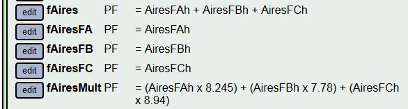
I forgot to tell you about the results I was obtaining. This is the outputs I defined:
And as I said, I’m getting the same result from both expressions, both under 1.
My question is more about what is the calculator doing. And it appears that the results are nearly correct. I lost the reference but I read that the PF should be the average of the PF in the 3 phases, which is the result in this example above. But I don’t know if that’s what’s being computed by the calculator or just a coincidence (Note: the values from fAires and fAiresMult are always the same except for changes on the second digit (e.g 0.95 and 0.94). Also, fAires and fAiresMult are almost always equal to the average of the 3 phases, and sometimes varies but didn’t record by how much (I will test it, just out of curiosity). In any case, you’re right that the PF results would be more representative. This is specially important in some circuits we measured earlier, were we found very different PF from different conductors of the same phase in a circuit.
Probably I will just skip this measurement at all. From what I’ve seen in our bills from the utility company, PF is not an issue at out facility.
Maybe I’ll do some more elaborate tests when I have more time.
Our service and facilities are 127V/220V. I’ve studied a circuit with 2 conductors per phase by installing the 6 CTs and then obtaining the fraction of power that goes through each of the two conductors in every phase. The ratio is not constant and varies with the total power (and I would assume temperature too), so I computed the ratios as the average of data obtained very minute over 5 days. It works well for the total kWh energy because everything averages out, but it varies for instant power, which is not a big deal anyway since max variation was less than 2%. Let me know if you need something else. I have a 7000+ row spreadsheet with all the data.
I can’t locate my notes from when I coded the PF script evaluation. It was more than a year ago. As I can best recall, I could find no definitive method of combining power factors from multiple circuits. Since Power Factor is essentially unitless, there were some varied opinions about what such a result represents, and some variation in the way to go about it.
What I seem to have settled on is a simple approach that is based on the equation VA² = W² + VAR². Essentially a right triangle with real-power and var as the sides and VA as the hypotenuse.
At each interval, IoTaWatt stores the accumulated watts (real-power) and VA. So all data must be derived from that. Voltage is typically available in the accumulators for the associated voltage reference. So you can see that Amps can be extracted by dividing VA by Voltage. and Pf can be computed by dividing W by VA.
But you want to know what happens when a function operates on multiple Pf operands.
So the way that works is that the script evaluator first runs the script twice. Once to evaluate Watts, and then to evaluate VAR. VAR is calculated as SQRT(VA² - W²). So if the script adds several inputs, the two values are the total Watts and the Total VAR. I visualize these metrics as the x and y axis in a phasor diagram, and not vector quantities. So they can be added and subtracted. I have no idea what multiplication and division between these values would mean, but my sense is that the multiplication by the scaling factors is OK.
So now that we have W and VAR evaluated, the result is computed as W / SQRT(W² + VAR²).
For what it’s worth, that’s how it’s done. As I look back on the discussion from a year ago, I would say that @Giraffe sorted this out and first suggested this approach. If you have any more question, better ask me fast, because I will forget these details after a couple of night’s sleep.
Power factor is a measure of the angle between the voltage and current or real and reactive power in a single phase circuit. It really does not make sense as a thee phase measure. If the 3 phase load is balanced then then the power factor is the same for each phase, if not balanced it will be different for each phase.
I can’t think of any use or value in creating a “three phase equivalent” power factor but maybe somebody out there has another view.
Generally in power system design its important to have load balanced across phases and ideally close to a power factor of one on each phase to get best utilisation of assets. I would be more interested in whats happening on each phase than some average power factor.
That all makes sense, and that’s why it seems to be working. If you divide total 3-phase Watts over total 3-phase VA you would get the total PF of the 3-phase circuit.
Now for the sake of discussion:
So that’s basically W/VA. Although I understoof before (long time ago) you were obtaining VA (and Watts) from basic measurements:
"For each measurement, IoTaWatt collects sample pairs of voltage and current for one AC cycle, defined as starting at the voltage zero crossing and ending after two more zero crossings. To compute real power (Watts) is the average of the products of voltage and current of each sample pair. IoTaWatt samples each AC cycle about 640 times at 60Hz. This is the way every digital power monitor I’ve seen works. So power factor is a product of the fundamental measurements, rather than a fundamental measurement itself.
Each time a channel is sampled (two or more times per second), the measurements are added to individual watt-millisecond and VA-millisecond accumulators. Every 5 seconds, those values are essentially turned into watts and VA by dividing the accumulated totals by ~5000ms. So regardless of the regularity of the sampling, the weighted average is a good integration of the power over the 5 second period."
Question: Are you actually computing VA as the product of the following?
Vrms = sqrt (1/n(Vsample1^2 + Vsample2^2 + … + Vsamplen^2) )
Irms = sqrt (1/n(Isample1^2 + Isample2^2 + … + Isamplen^2) )
In any case, it seems to be working
Indeed. The X’ss and Y’s can be added and subtracted and so that’s why it works.
I think it does. For example, the utilities company would penalize customers with low PF (under 0.9 in some places, but it varies).
Actually I’ve been over this the last few days (partially) and it makes sense if you see it as PF = W/VA. Since one can simply add watts from each phase for the total power, you can also add VAs for total apparent power. Then compute Wtotal/VAtotal for the total PF of the 3-phase circuit. That’s what I’m trying to do here, btw, compute the PF and compare it to the value on the utilities bill (Same with kWh and peak Watts, etc).
Agree. But you can still have some relative unbalance because not all of the loads (single phase) are ON at the same time.
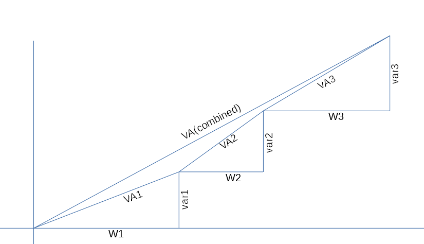
I don’t recall all of the reasons for doing it the way I did. But my recollection is that VA is a vector quantity and cannot be simply added. Going back to the graphic view, I see it this way:
So just adding all the individual VAs doesn’t produce the same result. I can’t say what any of this actually means as a metric, but I do believe that the PF being produced by the IoTaWatt calculator is not the same as:
That’s why it computes and adds the vars rather than simply adding the VAs which it has in hand.
This is certainly a valid calculation (the graph) if each of these circuits (1,2,3) are on the same phase.
If these circuits were on different phases then I think this calc gives you a weighted average power factor across the three phases. The utility may or may not use this for billing or flagging poor power factor or may use the worse phase. It a question that should go the particular utility as to how they do their calculation. The electronic revenue meter would have all the data by each phase.
If it was my utility I would calculate the power factor for each phase and use the the worse power factor for billing as ultimately it will be the limiting factor for asset utilisation of the distribution substation and avoids one bad power factor phase being hidden by two good phases.
I tried to compute the equivalence but I found out how the utilities company computes it.
Nice graphic, btw. Thanks!
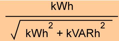
I checked and the utilities company computes the PF as:
So it’s total energy at reactive energy at the end. You have a point that imbalance should be considered but I don’t know why they don’t. The bill only shows the total kWh and kVARh and the PF.
Thanks!