Thanks Frogmore for the info. Sounds like it is something that is trial and error or if you have access to the appliance it may tell you. So for a Dryer, is it often the motor on 120v and the heater on the other leg of the 120v? Our dryer connection is a three-wire 240v connection and 30A double sized circuit in the breaker. In my drawings above, all the appliances are 240v (dryer, A/C, Pump, Range, and I assume future solar). I would assume I could also join the two A/C objects into one as one is the air handler in the attic and the other is the condenser outside. Both have a 240v connection to the box, yet they are a single object. That way I could potentially save on CTs if I could combine these two.
Wherever possible, I recommend placing the CTs of 240V circuits as diagrammed with one conductor reversed. There is no downside, it takes away the guesswork of whether there is a 120V component, and the input will show true power without the need to double it in the IoTaWatt.
So, there are two options based on your previous feedback where (not for sub panels) you can place one CT on one leg of the 240v circuit and double it, or you recommend the same with all 240v and sub panels to use the turn-around one leg option and no need to double based on reference voltage? I just want to make sure that I’m clear from the previous input above.
The best option in your opinion is to go with reversed leg (twist one phase) in the CT for all 240 based circuits in the panel?
It takes away any guesswork as to whether there is a 120V component. I don’t expect users to have the fundamental understanding of how these circuits and appliances operate, and I don’t think it should be necessary. So yes, On balance I think this is the best universal recommendation.
That said, an electrician would know whether any particular circuit is true 240, and there could be circumstances where measuring just one leg could be useful. For example, if the CT available is not rated for the full current of both legs, or if the panel is wired in such a way that it would require modification to add the reversed leg.
Consider a 10Kw solar inverter. The nominal output would be about 42Amps per leg at full output. Inverters are true 240V so you could use an ECS1050 on one leg and double it. To monitor both conductors would require an 82Amp CT like an ECS16-100 or SCT013-000.
I often over think things and I like that there are options that a little troubleshooting would not solve. Tweak a few things here, change a few things there. I was hoping to limit the number of CTs installed in my panel (being from the 1970s) it is quite tight in places and rather full. I wanted to get the most number of circuits monitored with the lest number of CTs.; as I’m sure everyone is wanting to do.
My thoughts are to use up 4 of the 14 to monitor mains (2x) and solar inverter (2x) as these are the more important items to have good numbers on. Consumption of energy and suppling of energy (via solar).
The remaining 10 ports could be used to monitor the two subpanels (2x) with one reversed leg (Barn/Garage) which gives me 8 remaining ports for things like the Burner/Hot Water, A/C, Well Pump, Range, Fridge, Dryer, Freezer. So , I would be back at the same plan with the number of CTs to cover the major items from earlier discussions.

Sounds like I would need to look at another unit to pick up all the smaller circuits if I wanted too in the future.
I suppose this discussion could go on forever, but I do think it has been productive and is a really good example of the kinds of decisions many users will face, so I’ll add a little more:
The solar only needs one CT.
Using the two wire method, you need to have a CT that is rated for the sum of the two breakers feeding the 240V circuit. So I’m guessing the Range, Dryer, possibly A/C will need more than 50Amps.
In my house, I monitor what I can with the 14 inputs, and then I have defined an output which is mains minus all of the monitored circuits. It’s remarkably useful. Here is my “unmeasured” usage for the past 24 hours:
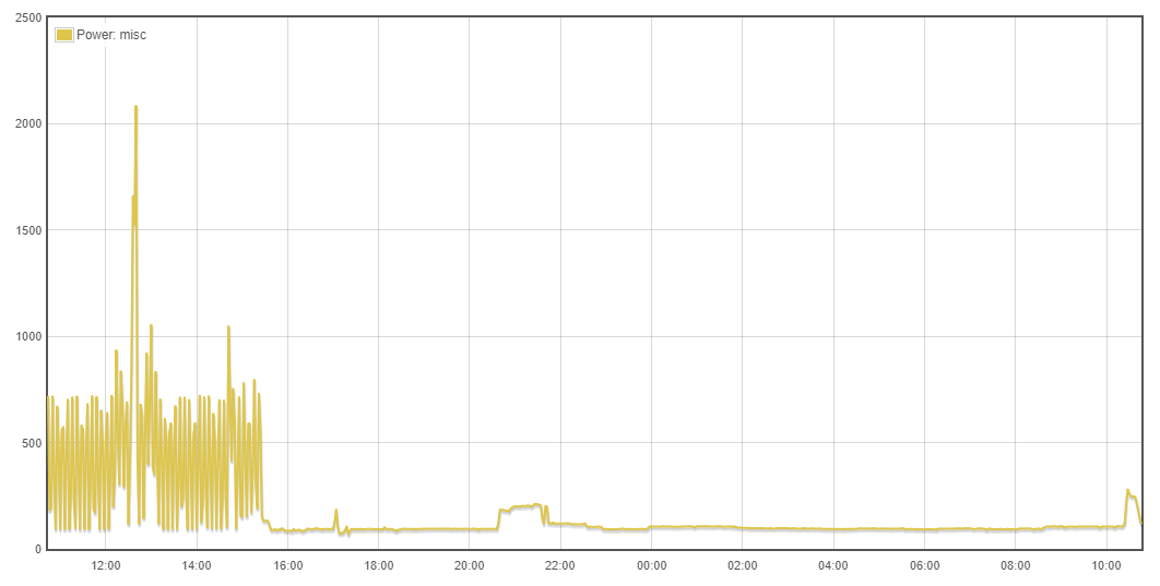
The baseload is about 80 watts and is composed of various 24/7 stuff like our Radon fan and some standby battery chargers in the garage. Even with large appliances switching on and off, this doesn’t vary more than 10W or so. What you see on the left is a dehumidifier that I’ve had to run for a couple of days in the basement. It apparently filled up and stopped about 15:30 yesterday. The blip at 17:00 is lights in the basement when I went down to feed the worms. The usage starting at 20:30 is outdoor lighting.
The point is that using this “remainder” method, you can actually see what is not directly measured, and decide if it’s something that needs it’s own dedicated monitoring. I’m of the opinion that most households can get on top of 95% of their usage with 14 CTs.
Here I’ve zoomed in on three hours of that dehumidifier portion:
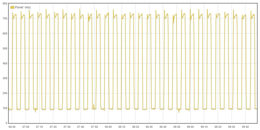
Bear in mind that this isn’t a direct measurement of the duhumidifier with it’s own CT. It’s my mains with all of the measured circuits subtracted from it. IMO the accuracy of the measurement is awesome. In each cycle of the device, you can see the inrush current and the exact same trend up as it heats up and uses more power. Then when it shuts down, the usage drops right back to my baseline load.
You’ll have to stare at it for awhile to make sense of it, but here’s that same zoom of the dehumidifier with the mains and a few of the more active circuits that are being subtracted from it.

3 Likes
Yes, taking a look at the remainder is helpful, as is looking at which “phase” it is on, or if it is a 240V load.
Bob, which dehumidifier do you have and how are you controling it?
Most dehumidifiers I have seen turn on the fan before and after running the compressor, which seems like a good idea, but turns out to actually not be one from an efficiency point of view. If you have the dehumidifier in the basement for moisture control (more than comfort) running it with such short cycles is not a good idea. It it the way most/all are setup, but it uses more electricity and stressed the components excessively. My first one lasted a season running like that and made the basement quite hot. My 2nd didn’t even last a season, but I got all my money back on that one  . I am now on my third one and it has been running since November. I have a custom control system that turns it on and leaves it on for a minimum of 30min. I have the dehumidifier set to keep the humidity at 35%, which it likely could never achieve. I measure the water output with a modified rain gauge and now have an idea of how well things are going. I did this originally to see when the dehumidifier was loosing it’s refrigerant charge, since that was the failure mode of the previous two, and it was visibile in the power utilization. It takes less power to run the pump when there is less/no refrigerant. I first discovered this looking at the remainder signal. Now, I have a Sonoff POW that measures the power of and turns on and off the dehumidifier. I have a sensor on the other side of the room that measures the humidity. I have a flow in NodeRED that gets the power measurement from the POW via MQTT and the humidity from another device and then makes the decision to turn on/off the dehumidifier by sending a command to the POW.
I’m a graph and data guy and I love the images you have attached along with the visibility they provide. Way too cool. So, in your opinion, you would just buy the two 200A CT for the mains and the rest (12) 100A CTs just to be safe and make sure I would not exceed the load? I love the discussion and I agree it could go on for ever, but as you said, this is very helpful to me and I’m sure future readers, etc. Love the interaction and sharing.
Can you PM me when you have time and we can talk about the CTs and a unit when available? Or, if I can get on a list of users when they come available?
It’s a cheap old one that I use for about ten days a year. My approach to basement humidity is to eliminate the source rather than try to remove excess. I admit that’s not an option for many folks, but it works for me. My house tests out at 0.10 air changes per hour, so keeping the basement sealed keeps out most of the moist summer air that can condense on the cooler surfaces.
You’re right that there are better technologies for dehumidification. I like the “heat-pipe” approach which can cut the energy use in half.
Where could I buy those? (I’m not in US)
Thanks
I bought my CTs direct from @overeasy here in the US and I see you do not have this option. Hearing from others, these specific CTs are a bit more difficult to source unless you are able to find a local distributor. Unless you purchase in quantity, I’m not sure you can get them direct from the manufacturer. I have also heard of a few that purchase in volume and sell to others in their area who also have IoTaWatts.
You can find them on Alibaba. They say minimum 30 but everything is negotiable on Alibaba.
Looking around I found also the selection of the class of the CT, maybe it is so obvious that I did not see mentioned.
As for example looking for the ECS10-50 I got proposed to have the class 0.2 and looks like that the precision.
Another point I would expect that is better to also have in combination with a better class to use the full range of the 50mA output (than 33 or 36mA) correct?
Yes, there are many output options for all of the Echun CTs. For the ECS10-50 the model configured for IoTaWatt is 50A/50mA (1000 turns). I wasn’t aware that there is an accuracy class 0.2 available for this CT. The model available at the stuff site I believe is class 1.
I asked them the ECS10-50 as base and they offered the class 0.2.
I’m afraid that with this I will have to determinate the phase shift?
Do not generate extra work to determinate phase shift on what do I have to stick?
What do you think about the comment on the protection diode?
tem No.: TYKCT-YA01-50A/50MA
Description:
Inner Hole 8mm,
Current Input: 50A
Current Output:50mA
Accuracy: 0.2
Lead Wire: 1800mm lenght, with 3.5mm Jack Connector
Kindly note above offer ct is without protection diode. And according our experience, for 50A input /50mA output, the ct will with 1000 turns winding, without protection diode is ok.
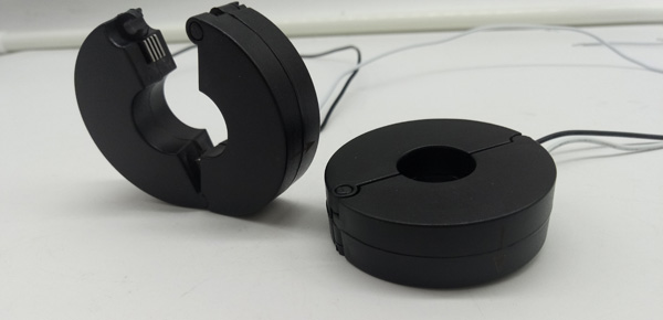
Not that there’s anything wrong with these CTs, I have no idea, but what is pictured is not an echun ECS1050.
Yes. I posted how to do that for another user yesterday.
They protect the CT when unplugged and have nothing to do with normal operation. Not aware of any reason why these could not need them while unplugged. Usually, you can hear a CT buzzing when unplugged without protection.
What would be the best value of the voltage output 0.25V, 0.333V, 0.5V, 1V, 2V?
Do you see an issue if I would use a 40A/100mA to monitor a cable of a fuse with max 16A?
The idea would be to use the one with 100mA and not 50mA to have better resolution on this range for the used range.
Those outputs would be voltage type CTs and you would need to remove the burden resistor in the IoTaWatt. I don’t recommend that.
These are current type CTs and different from the voltage type above.
To answer your question, I don’t see an issue, but I also don’t see an advantage.
I know this “full scale” philosophy is promoted for other energy monitors, but I just haven’t been able to see any imperical difference to support it with IoTaWatt. Sure, you probably don’t want to use a 4000 turns CT for low current, but 400 vs 800 does not improve accuracy more than the variation you will get in calibration from CT to CT.
Hi Bob,
What are the actual model numbers of the EChun CT’s that you have used for configuration?
I got some ECS1050-L59E and they work perfect.
I also got some ECS16100-L120H but they do not report any value at all. (tried 3 different ones and they are all the same)
ECS16-100-L59H. Their data sheet doesn’t breakdown the configuration portion of the model. I got this from my invoices. When I order I specify the electrical characteristics. 100A:50mA.
I suspect that you have bought voltage type CTs.