Hello,
I’ve decided to switch from the OpenEenergyMonitor community to the IoTaWatt community. The discussions so far can be read under the following treets:
I have a three-phase system with solar system and normal consumers. At phase A a VT is connected. 3 CT are connected to the three phases of the solar system, 3 CT are also connected to the three phases of the main supply line.
I have now measured 1 month again. The measurement of the solar part is almost 100%. But the measurement of the consumer does not correspond with the electricity meter of the electricity plant at all. IotaWatt measures about 50% more energy than the meter from the power company.
Today I made a try. I switched off the solar system and started a 15 kW compressor. IotaWatt then displayed a power factor of 0.80. Then I switched the solar system on again (about 5 kW power) without compressor and received a Pf 0.99 . Then solar and compressor together. IotaWatt then displayed no Pf .
I measure with a VT with Derived Reference. Sensor installation according to type 2.
I suspect that the power factor is not measured correctly on two phases. I do not know what I can do.
I’ve followed this problem, and I’ve seen the photos of the installation. There are a number of questions that I have, but rather than do that, maybe some graphics will better reveal the problem:
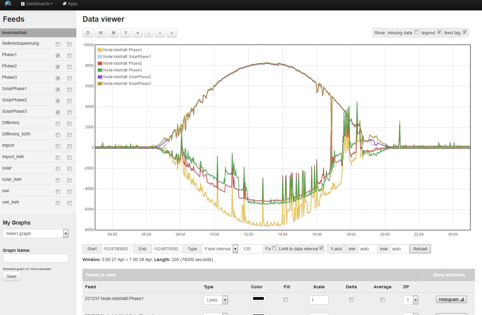
Using the graph app on IoTaWatt, could you plot your phase A main and phase A solar for one day with good sunlight and post it.
Then do the same for phase B and again for phase C.
After I see that, I will probably have some more specific questions. My sense is this will have a simple solution once we figure out what’s wrong.
I have a suggestion or a question: My old energy monitor had only CT’s. He had no reference voltage measured. I had to specify the voltage in the configuration. If I compare other energy monitors, eg. smappee, these systems also have only CT’s and no reference voltage. For a single-phase system, one can still take a reference voltage as in IotaWatt. But even with a three-phase system, this is almost impossible in practice. One would have to mount three sockets for the three reference voltages in the control cabinet, which is very costly. Would it not be possible to operate IotaWatt analogously to the other systems without a reference voltage? One could indicate, if one wants to work without reference voltage, with one, two or three reference voltages. Without reference voltage, one could even specify a voltage in the settings. I think many people could live with it well. What do the developers think?
This information is useable, but to be clear, it’s not the same as from IoTaWatt. The data points in this graph from Emoncms are the 10 second averages of power sampled every 2 minutes. The same IoTaWatt plot would be the 2 minute averages every 2 minutes. It removes spikes and anomalies, so that’s why I prefer to use the IoTaWatt data. It is possible to get averages from Emoncms, but you have to ask and wait for it.
That said, you don’t need greater accuracy to see what’s going on here:
As you said, the solar measurements are perfect. The outputs to each of the three phases lie directly on top of each other, as they should, when the inverter puts out equal power on each of the three phases. You have verified that corresponds to the inverter’s record of power output. What this tells me is that the derived phase reference is working well.
Turning attention to the bottom of the graph, the power flow through the mains, there is a clear problem. This curve dips almost as a mirror image of the solar generation because the bulk of the power is being exported rather than used in your home. You might expect some variation in the three phases due to different use loads, and there is some of that, but the overwhelming difference between phase 1 and the other two is proportional to amplitude. If the difference were due to load, there would be a fixed difference on the y axis. So phase 2 and 3 are reading low.
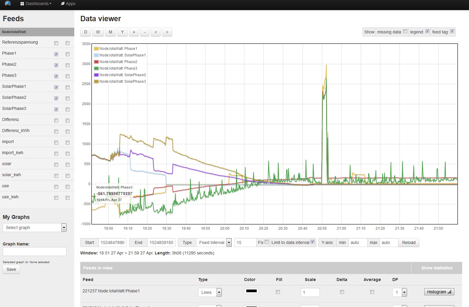
This problem is also evident in another way on the second plot that you posted in the evening, after the solar generation is taken out of the mix. Note the compressor cycle at 20:50. The power imported to run the compressor is greater for phase 1. These should be equal.
It’s possible that the phase 2 and 3 CTs are not properly seated, or just defective, but I doubt it. I think these differences are being caused by incorrect phase reference for the phase 2 and 3 mains. This can be a simple or compound problem, so I’d like to deal with it methodically.
First, can you check to see that the phase 2 and 3 CTs are both oriented the same as phase 1. That is to say the arrows on the top of the CT are all pointing inward toward the house or all pointing outward. If they are reversed, it is a simple matter for IoTaWatt to correct in a single phase system, but in a three phase system it is impossible.
If they are different, fix that and take another look at the power readings. If they have increased significantly, that was the problem.
If they were properly oriented to begin with, or they were reversed but there was no significant increase, then the two are likely assigned to the wrong phase. You can change that in the input configuration tab by simply selecting phase B instead of C and C instead of B for the two CTs.
If you find any of this applies, then run it for a day and post the same plots again.
If none of the above applies, then we’ll take another approach and start swapping things - in a methodical way.
I’ve don’t know what monitors you had, and I’ve only come across two that do not use a voltage reference. The one commercial monitor that I read up on assumes a power-factor of .92. Probably a reasonable assumption, and over time will yield long term energy (kWh) accuracy to the extent that the average power factor is near .92. It will be way off on power (watts) anytime the power factor gets away from .92, particularly when it goes lower, as with motors running at .80 or so.
They are measuring apparent power. They de-rate what they report by the assumed power factor to estimate real power. You’re right in that for some people it’s close enough. One of the Emontx products, I believe, has a mode where it runs on battery and reports apparent power, but I think they call it what it is and don’t try to de-rate it and call it real power.
It’s important to note that although we call it a voltage reference, the VT’s most important function is to be a phase reference. That’s the difference between real and apparent power. Real power is always less than or equal to apparent power, and it’s primarily a difference in phase between the voltage and current that determines that difference.
To your suggestion of having the option of using 0,1 or 3 VTs, IoTaWatt can do 1 or 3, but does not attempt to do it without a VT. I’d have to ask why you would pay serious money for a power meter that doesn’t have a phase/voltage reference when you can get a piece of junk that doesn’t use one for a lot less money?
The cables are allmost to thick for this CT’s, I had to press them over the cables. It is a good chance that this is the problem. On the solar part cables are thinner. I will order the bigger CT’s and try again before wasting your time.
Direction of CT’s should be o.k., otherwise the curve would be on the positive (or negative) side.
Thanks anyway for your great job.
That could well be the problem. The SCT019’s have a 19mm opening. In the USA I will be offering eChun ECS16100. These are 100A CTs with 16mm opening (SCT013 has 13mm opening).
That’s only true in a single phase system and on phase 1 in your system. In your case with phase 2 and 3 and derived phase reference, it would cause the power to be about 50% less and depending on the circumstance would be the same or opposite polarity. You should check that as I explained before going with new CTs.
Ff[quote=“hph, post:9, topic:116”]
Orientation is correct, I checked it today. I ordered 3 bigger CT’s and will come back after mounting them.
[/quote]
It would be worthwhile also checking to see that the mains phase is correct. Those should be B and C and if incorr3ct would also produce about 50% inaccuracy. You can verify they are the same as the inverter CTs on the same circuit, or you could just swap them and see if the power values increase significantly. That is change phase 2 to C and phase 3 to B.
I have a doubt with the three phase (direct method - using 3 ac-ac adapter)… For this setup to work i need to connect each of the ac-ac adapter to a socket from each phase?
EDIT: (Nevermind) i’ve just read it in the wiki.
To use Direct Reference three-phase power measurement, it’s necessary to first obtain and install two additional VTs (total of three), and to locate each of them in a receptacle supplied by a unique phase.
The real question is whether you need three references. The nice thing about IoTaWatt is that you can try it with one and see if it’s accurate enough for your needs (I think it will be). If you then want to add two more VTs, you can using the same equipment. You would need to remove two resistors from the internal circuit board in order to add the additional VTs and get an adapter.
Hi overeasy.
I tried to buy the IoTaWatt Direct 3-phase adaptor kit, but it is unavailable.
1.- Do you know when it will be available?.
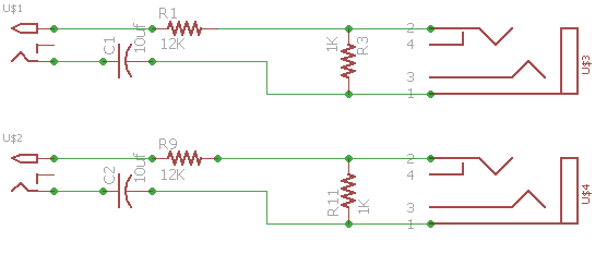
2.- Can you share the schematic of 3-phase adaptor?.
Thank you. I am planning to buy around 4 units.
My address:
Av. del Bosque 1145, colonia el Bajío, Zapopan , 45019, Jalisco, México.
Tel: (33) 3777-3600 Fax: (33) 3777-3609
I recommend 0.5% resistors or better. For the capacitor, I use +/-10% 25V. Be sure to use 10uF as it does affect the phase of the voltage reference and the IoTaWatt is calibrated for that value.