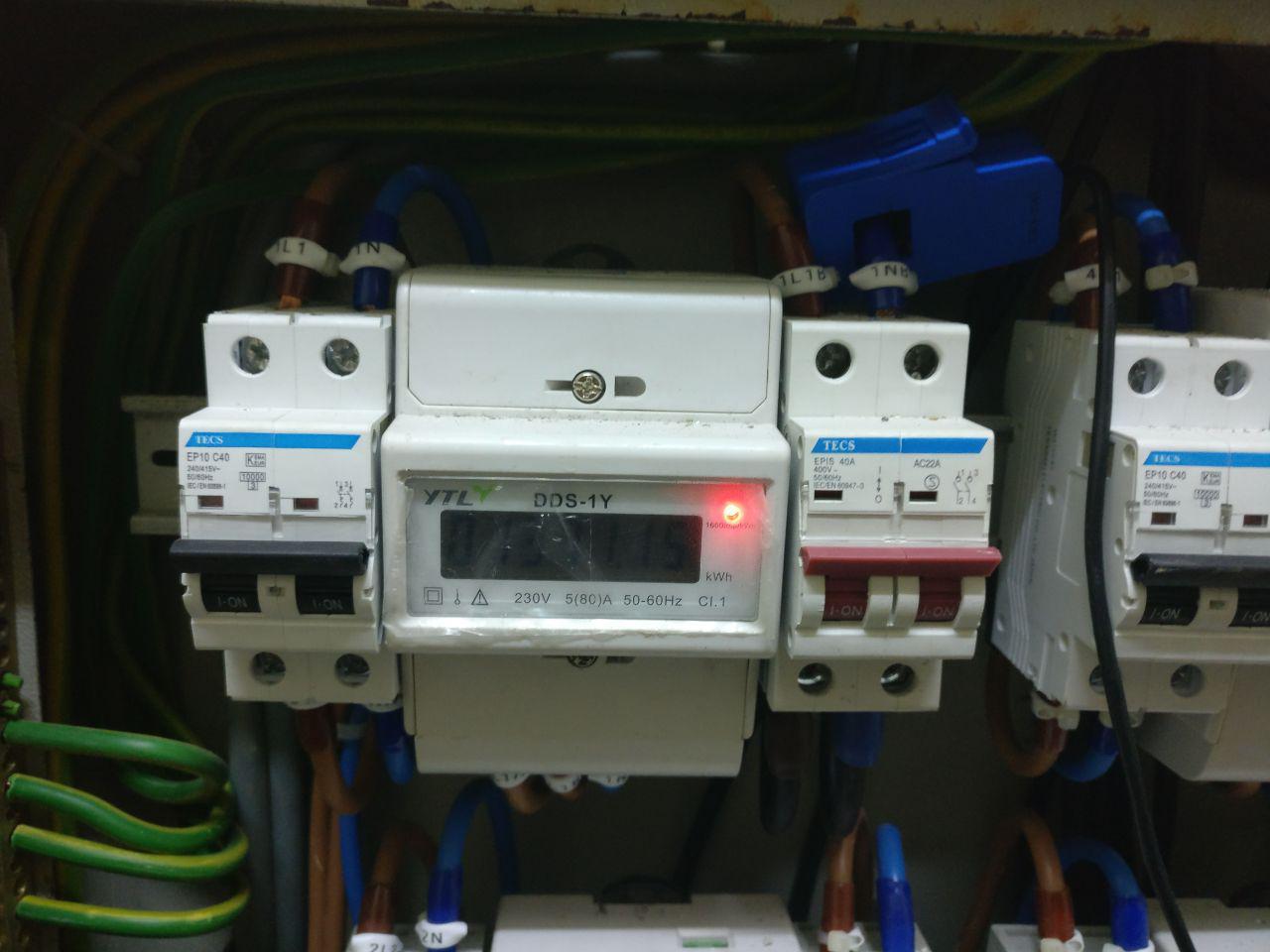
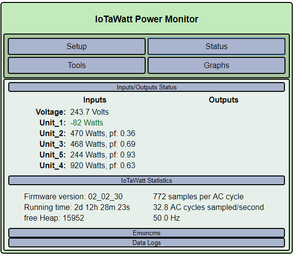
I’ve just set up an IoTaWatt for 5 different units in my house. All the units are running fine, however, one unit usually has a negative reading of around -200 Watts but when I turn on the water heater it jumps to around 1100 Watts. The CT 100A is clamped to the live output from the mains.
Very nice installation. The equipment is all foreign to me (North American) but I’ll take a shot at it. First, can you tell me what country this is?
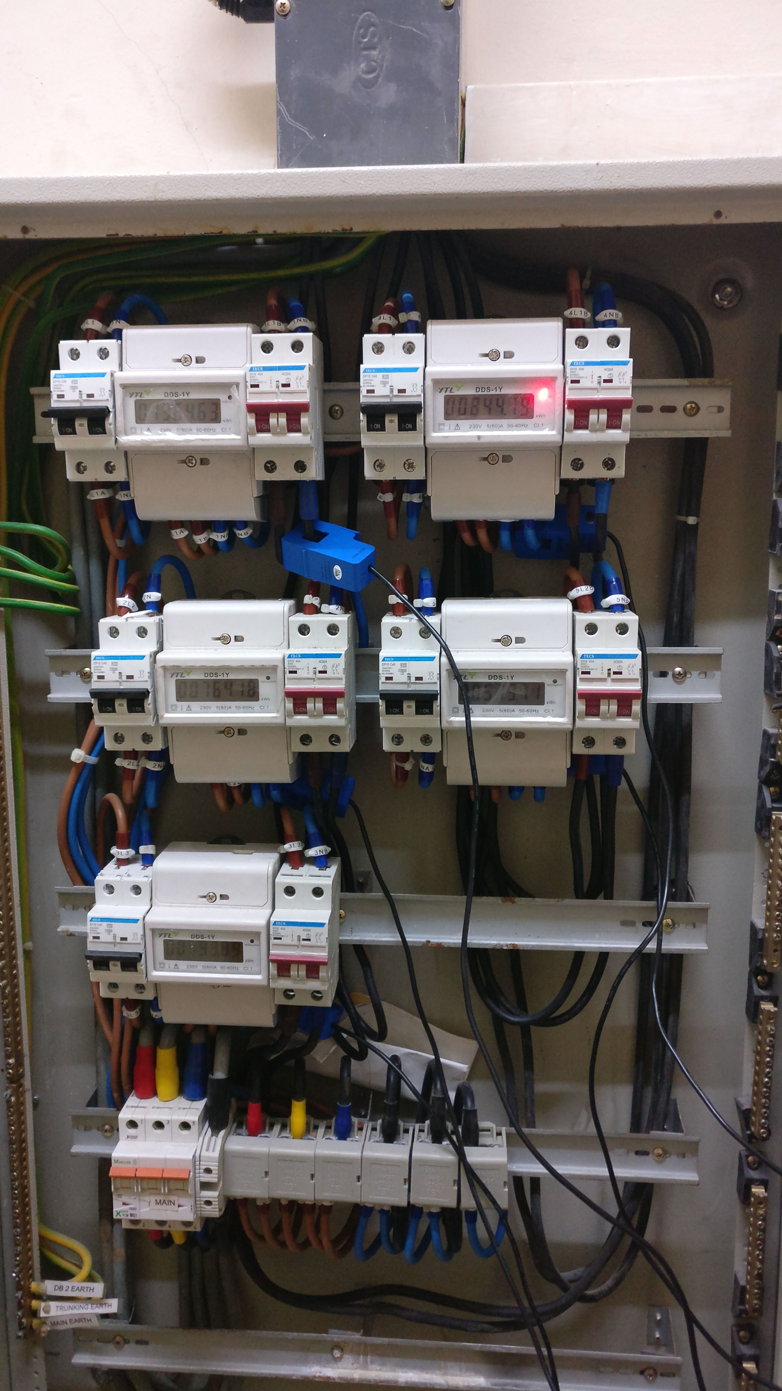
It looks to me like the mains are in the lower left, color coded Red, Yellow, Blue. They then go to some splitters on the right to produce single 2 outputs for L1 and L2 and 1 output for L3. L1 feeds units 1 and 4. L2 feeds units 2 and 5. L3 feeds unit 3.
That doesn’t appear to be the case. It’s not clear for all units, but for sure units 1, 2 and 4 appear to be clamped around the neutral. I’m not sure what this does, but the neutral is common to all of the units, and possibly there is some kind of reverse current flow.
I’d like to verify that you have the three-phase configured on the IoTaWatt. Could you post a screen shot of the inputs configuration menu, and two of the status display - one with the negative value, and one with the positive value from the water heater?
While it appears to be true that each unit Is serviced by only a single phase, your system has three-phases and you want the IoTaWatt to measure power on each of them. So you will need to use the three-phase capabilities of the IoTaWatt.
This seems to be a clean straightforward setup, so the phase assignments should be easy to figure out. Can you determine which unit the AC voltage transformer is connected to?
Hello, thanks for the reply. Apologies for the long silence, work got really busy for me for awhile.
However, I’m not very well electrically trained and will need some professional on-site help to get things going. I see the three-phase option on the settings dashboard of the IoTaWatt but do I need more CT sensors to get it setup?
Fff [quote=“keithle, post:7, topic:263”]
However, I’m not very well electrically trained and will need some professional on-site help to get things going. I see the three-phase option on the settings dashboard of the IoTaWatt but do I need more CT sensors to get it setup?
[/quote]
No, you do not need additional equipment for the simpler method of measuring three phase, but it will require someone that understands how it works to install the existing CTs appropriately and configure the IoTaWatt to know which of the three phases each unit is connected to.
@overeasy, thanks for the pointer. I’ll do some reading up. On a quick note, I have a small update.
I had the electrician come over yesterday to give the IoTaWatt a quick look. He measured the amperage with a AC clamp meter and the readings from it showed that there may be a calibration issue with the IoTaWatt (not blaming the firmware but it might be something I may have missed). Eg. A reading of 3.06A on the clamp meter but the IoTaWatt shows (630 Watts instead of the ~730 Watts.)
I had him checked on the Voltage readings for the AC-AC Voltage Transformer (VT) from the wall socket and that is correctly calibrated. I’m guessing that this difference in readings (CT vs AC clamp meter) is causing the negative values.
Maybe a problem, maybe not. Mixing RMS Amps and Watts is apples and oranges. When you multiply RMS Volts by RMS Amps, you get apparent power, which is expressed as VA. The calculation for Real Power, expressed as Watts, is more complex. The relationship is called the “power factor”. (PF). PF is defined as real power / apparent power. So lets assume 230V (RMS). So multiplying 230V x 3.06A gives 703 VA. If IoTaWatt reports 630 Watts, then the PF should be 630/703 = .90 . Which is common. IoTaWatt should report PF along with Watts, so now you know how to translate that.
You can also define an output for that channel with units = Amps. That will cause the RMS Amps that IoTaWatt measures to be displayed on the status screen.
The negative values are caused by the voltage being 120 or 240 degrees out of phase with the current. IoTaWatt can numerically shift the voltage to match the phase, but needs to be configured to know which phase each of the units is assigned to. That is called “derived three-phase” in the wiki, because the IoTaWatt “derives” a phase shifted voltage signal from that of the phase that the AC-AC transformer is on.
@overeasy, thanks alot of the info. The learning section from OpenEnergyMonitor takes some time to read up because it throws some terminology that I’ve not come across or was from the earlier years of schooling.
I’ve come to realise that and understand/infer abit more. From what I’ve gathered, despite my 5 “units” being on single-phase power, my mains is a 3-phase supply and each “unit” is connected to one of the 3 phases.
Moving forward, I’m guessing I could use the DB’s wiring to identify which phase each “unit” is on? However, I’m not sure which phase the VT is on. Can I use that as a “base” and change the rest of the “unit” phase to get an accurate reading?
Can I verify that the AC clamp meter is measuring RMS Amps and power companies use VA?
The incoming three phases are color coded red-yellow-blue, and the neutral is black. That’s a common scheme. From here on I’ll refer to the incoming three phases by their color.
By the picture, your main breaker at the bottom goes to some DIN mounted splitters. Phase-red appears to go to units 1 and 4. Phase yellow appears to go to units 2 and 5. Phase blue appears to go to unit 3.
Each of the units has a CT connected somewhere, but I can’t see all of them in the picture. What I can see is that the CTs on unit 1 and 4 are on the neutral lines, and that they are not oriented the same. The current can be 120 or 240 degrees shifted from the VT reference, but also if the CT is reversed, that adds (or subtracts - same thing) another 180 degrees. The result is that there are many different combinations of incorrect installation, and only one correct one.
The starting point is to identify which unit, and thus phase, the VT is on. IoTaWatt uses the terminology phase A, B, and C to identify phases. By definition, the phase that the VT is connected to is phase A. Once we know that for certain, the number of possibilities goes down.
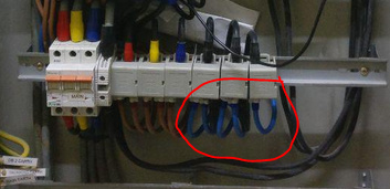
The next issue is making sure all of the CTs are oriented the same way. There is an arrow on the top of the CT. If you want to connect all of the CTs to the neutral for each unit, that’s OK, but you need to have them all going the same way. Probably the easiest way to accomplish that is to put the CTs down the bottom wher ethe various neutral wires are all together.
I would recommend that you have the electrician do this. If you try this yourself, at least turn off the main breaker to the left. That will shut down all of the units, but is a small price to pay for safety.
When connecting the CTs, insure that they all point the same way, either toward the splitter, or away from the splitter. This will also give you more wire to work with as the CTs will all be together at the bottom.
The neutral wires, from left to right are probably Units 1, 4, 2, 5, 3. But they will be labelled as 1N, 4N… etc.I can’t read the labels in the picture but I can see that they are there.
Feed those CTs into the corresponding inputs on IoTaWatt.
Now you need to determine which unit the VT is connected to. You can try to trace the wires, or see if they are labelled, or you can simply turn off the main for each unit one by one until the plug goes dead. Note which unit that is.
Now go to the input configuration screen and check the box Enable derived three-phase.
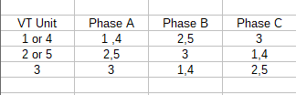
All of the inputs will now show as being on phase A. Edit each unit to set the phase as follows:
Go to status display and see what you get. The unit(s) on phase A should be correct. They may be negative, and if so, reverse the VT in it’s plug if possible, otherwise, just unclick the “allow negative values” on all of the inputs so that IoTaWatt will automatically reverse them. You will see the little ↺ sign, but that’s OK as long as the power is correct.
The units on phase B and C may still not be right. The incoming phases may be in a different order. If that’s the case, you would probably see power factors less than .50 on them. If that’s the case, change the Phase B units to phase C and visa-versa.
Give that a shot and let me know how you make out.
You can verify the RMS Amps with the electrician that owns the meter. I’m pretty sure it will be a true-rms meter.
By “use VA” I’m assuming you mean for billing. I’ve never been to Singapore, but all of the electric meters that I have seen measure real-power (Watts). They do not measure VA. Those submeters that you have for the five units read out in kWh (kiloWatt hours).