Setup for 3Phase Monitoring - Continued from eMonCMS Community Forum

Background:
Have just moved to an older property in Aussie Bush.
3 phase power with some old 3 phase equipment and I am trying to get a handle on whats actually running and ultimately what costs what.

I have purchased an IotaWatt with 14 x SCT-013 CTs and purchased credits with Emoncms.org and can log data ok. OverEasy has helped me a lot with getting my outputs from my outputs to setting them up as emoncms web server inputs so I can sum them before logging. :grinning:

What am I measuring?
3 Phase Input power to property (3 x CTs)
Solar Power Generation (1 x CT)
Hot Water (1 x CT)
Shed Power Board (3 phase, 3 x CT)
Garage Power Board (3 phase, 3 x CT)
Air Con (3 phase, 3 x CT)

Total of 14 inputs used and accounted for.

Examples of Configuration below:

Status

Inputs

Outputs

Emoncms

1 Like

Notes and observations:

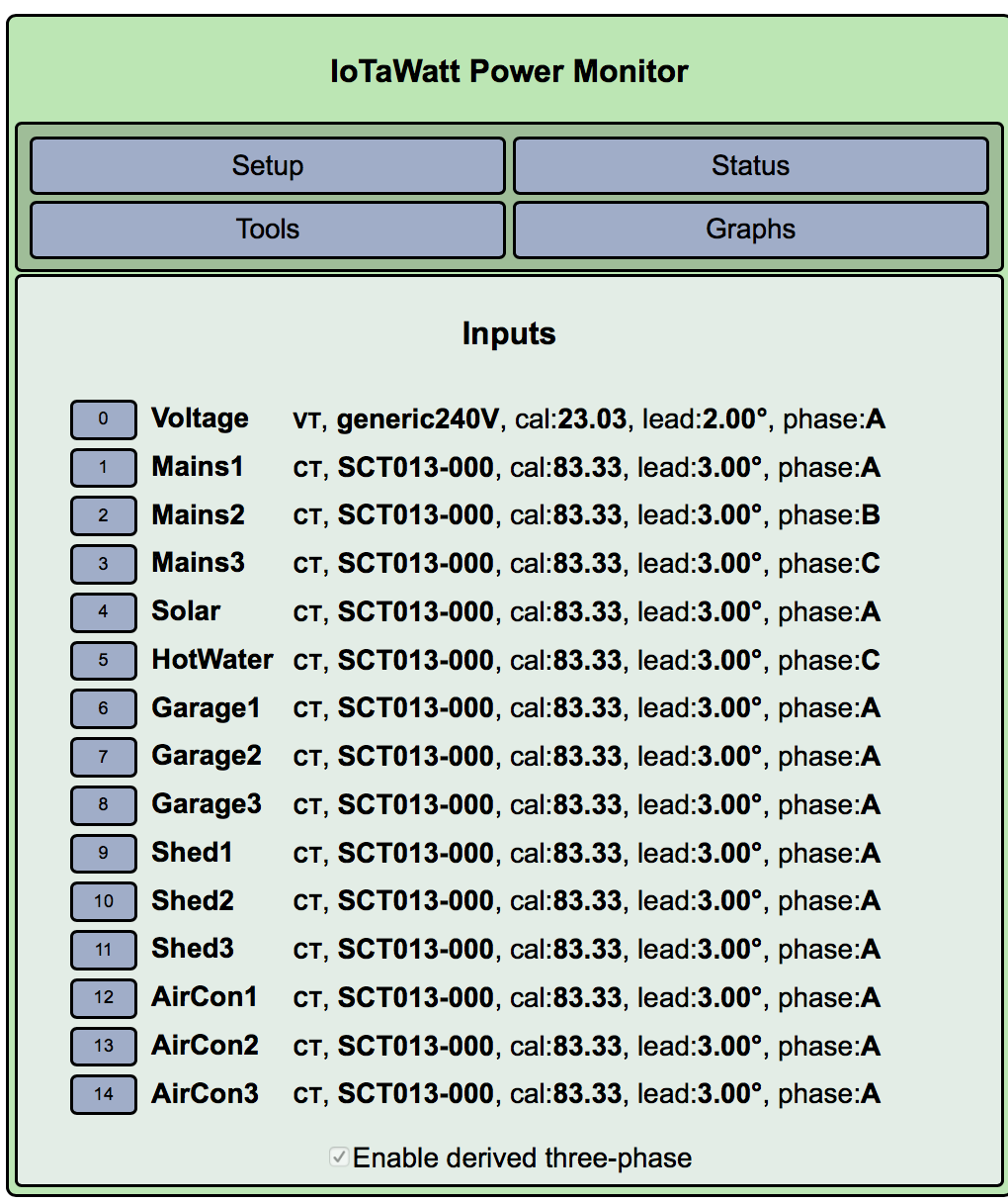
Voltage Power was calibrated, tested and is correct.
From the panel in the Solar Unit (CMS 2000) I can see that the voltage in the Solar unit reads about 10v higher (246 vs 236.)

The solar tells me I am making 40W overnight. This is odd as I have checked my meter and its not making power. I will need to investigate this further.

Keep in mind that the 3 phase goes to “sub boards” which provide individual phases/circuits to the AC and SHED.
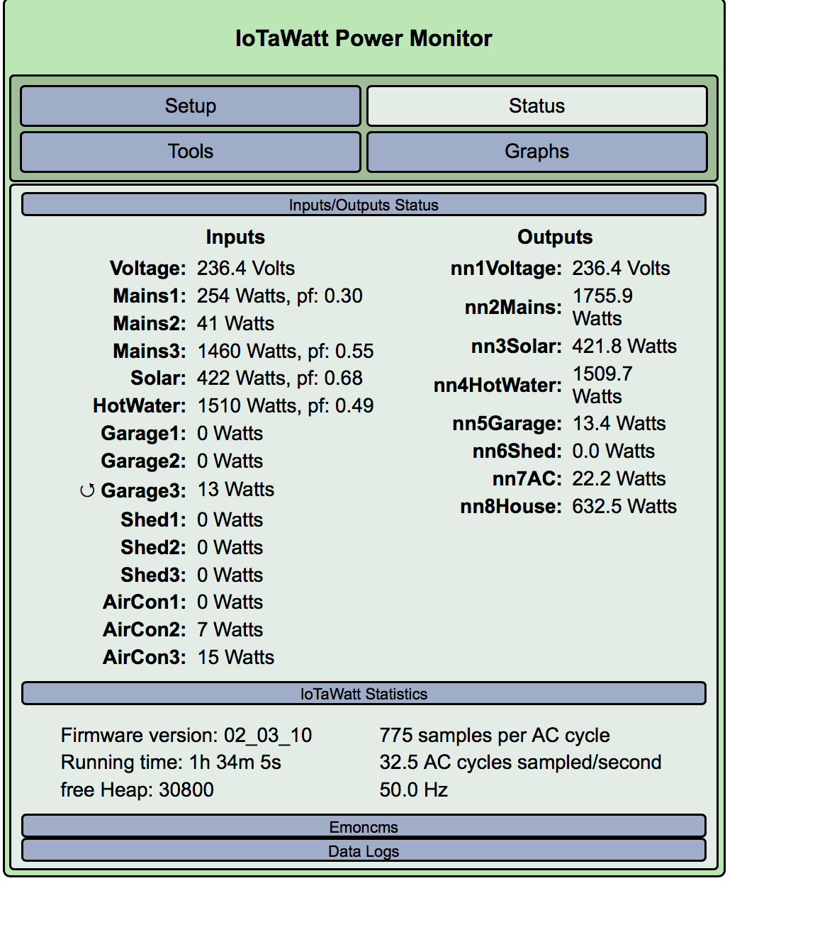
For example in the case of the AC
Phase 1 is the compressor (about 1500w)
Phase 2 is Internal power/wall box etc (15w)
Phase 3 is the fan (about 330w) and compressor (about 1500w)

I can get some screenshots with both AC, SHED or Garage (SAUNA) running so you can see usage.

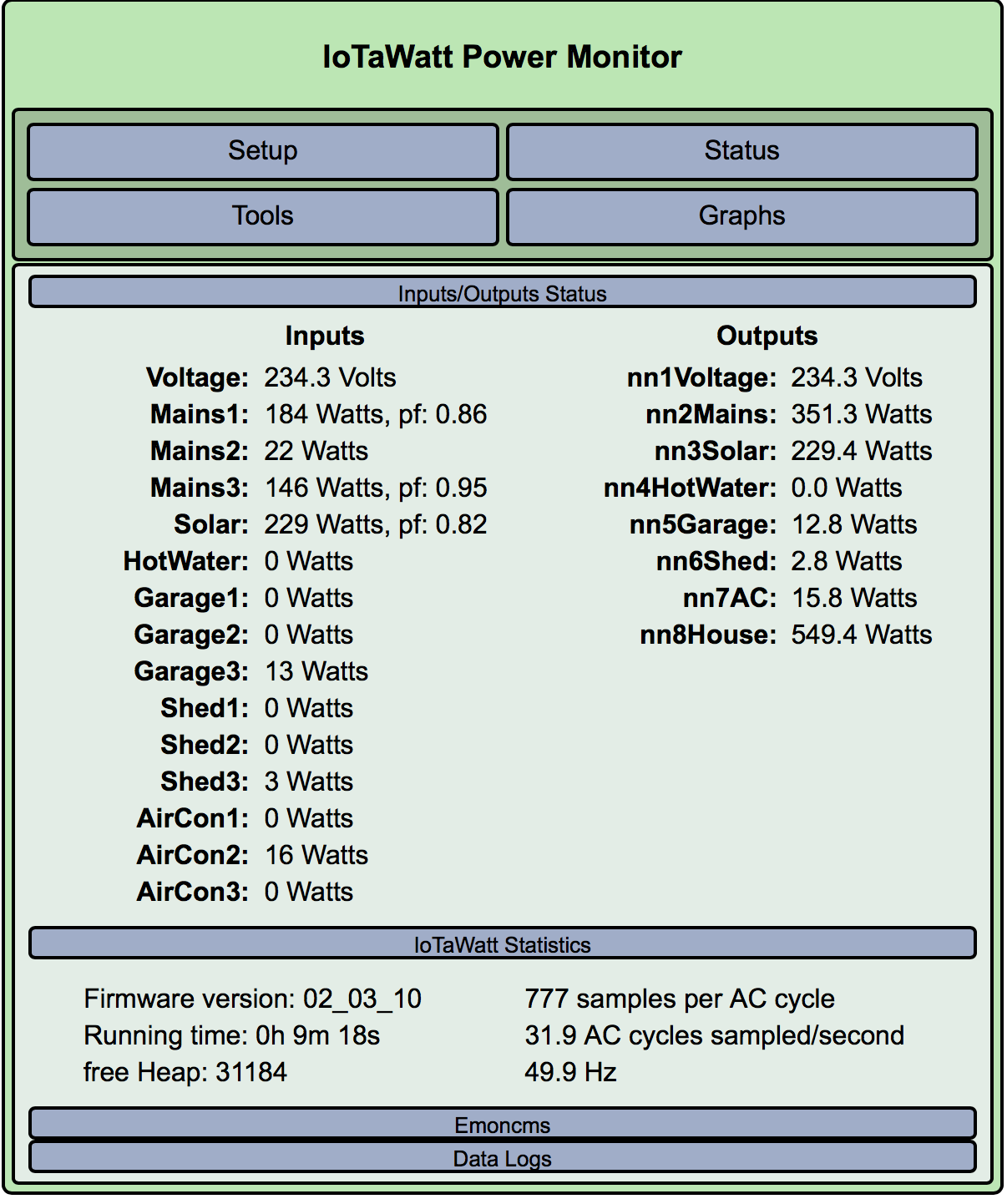
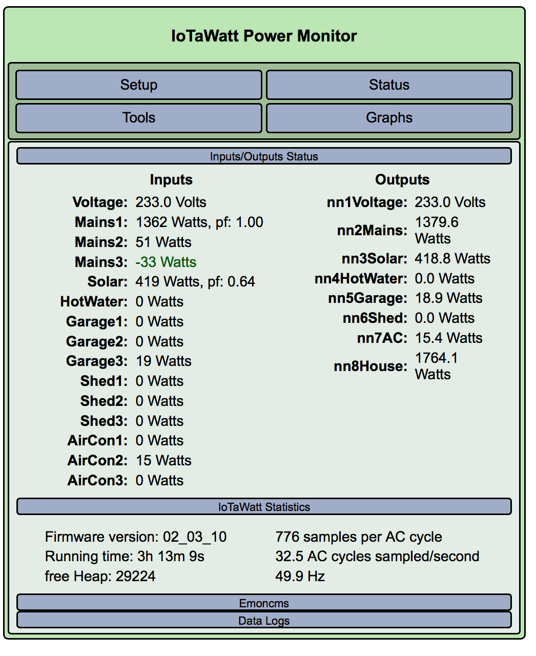
To answer questions raised in the other thread:

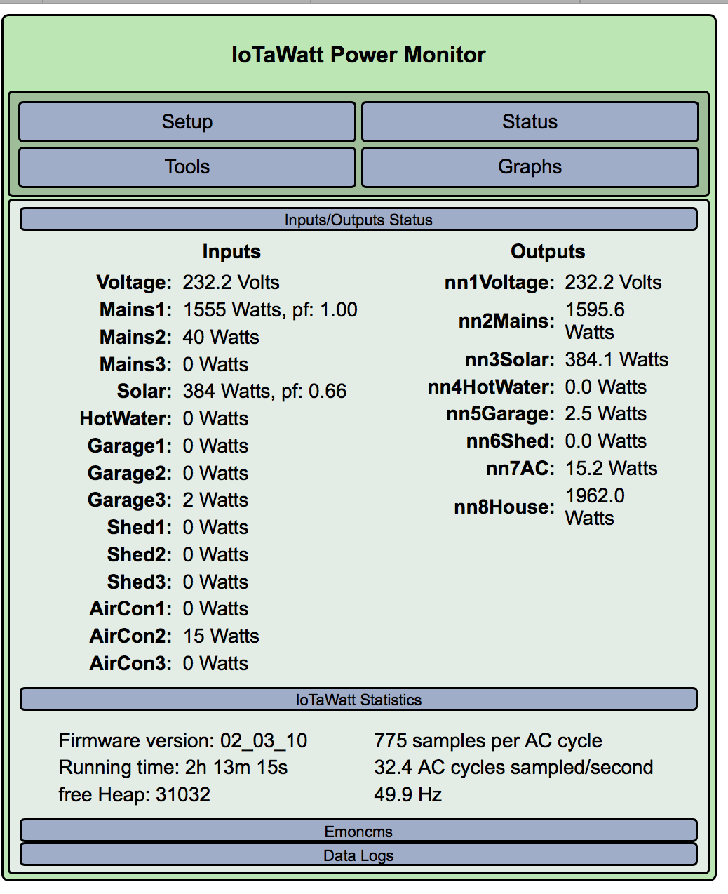
That doesn’t look right. Some of the glaring red-flags are the 0.06pf on Mains2, the 0.67pf on Solar, and the imbalance of the AC phases.

Lets work through it. Very happy to learn and then be able to assist others once I have some knowledge though see my above note re imbalance of AC phases.

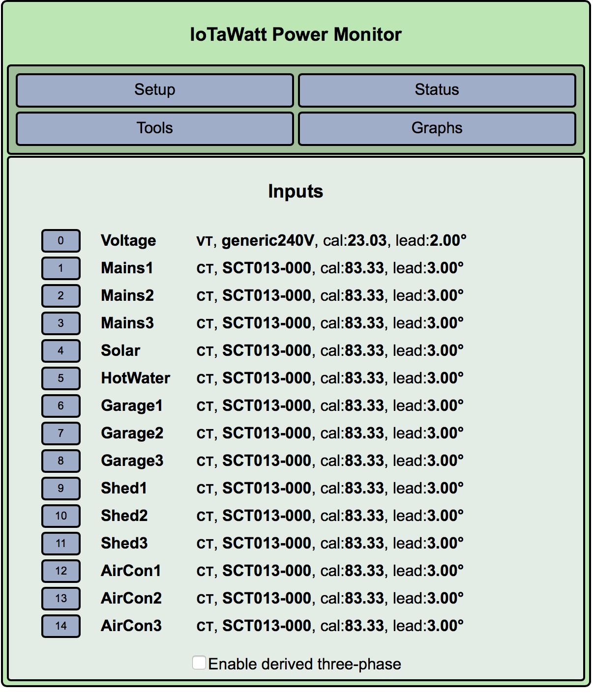
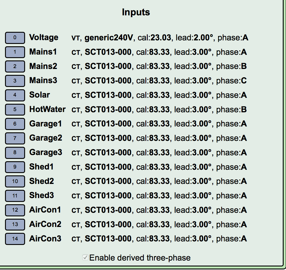
This configuration looks eerily like the one I posted earlier as a representative config for explanation purposes. Phase assignment there isn’t necessarily what you have. There are a lot of incorrect combinations, and only one correct one. Do you feel lucky today?

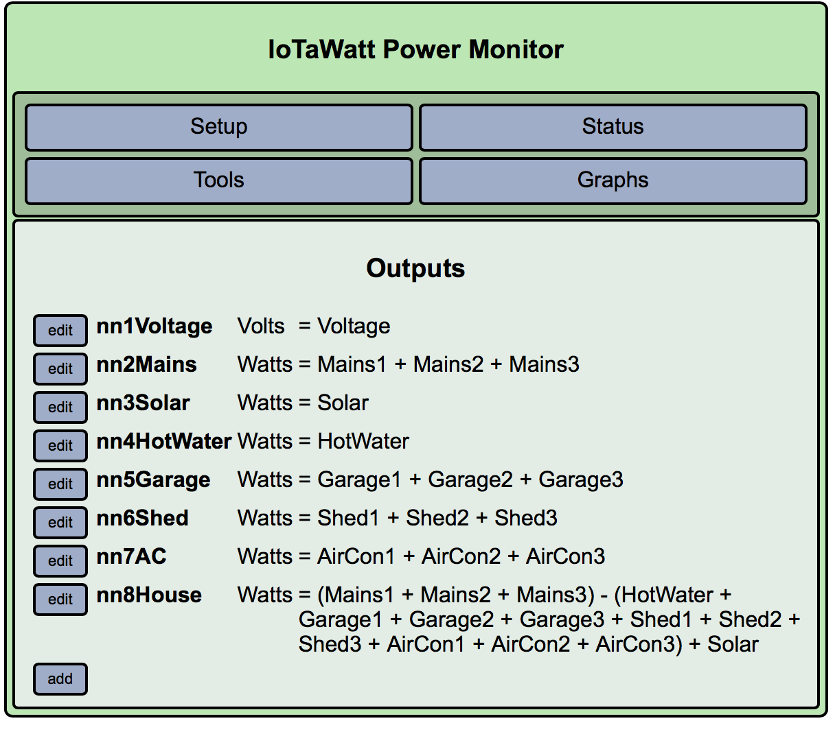
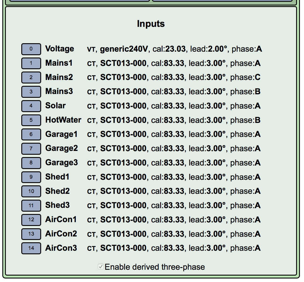
You happened to come pretty damn close to what I had configured originally. The difference was that my catch all was for the house. My logic was that if I monitored mains inputs, solar and everything using power then whatever was left was house. I don’t mind that its not 100% accurate as whats in the house is pretty much consistent and not much I can turn off - eg big costs are likely to be AC and Garage.

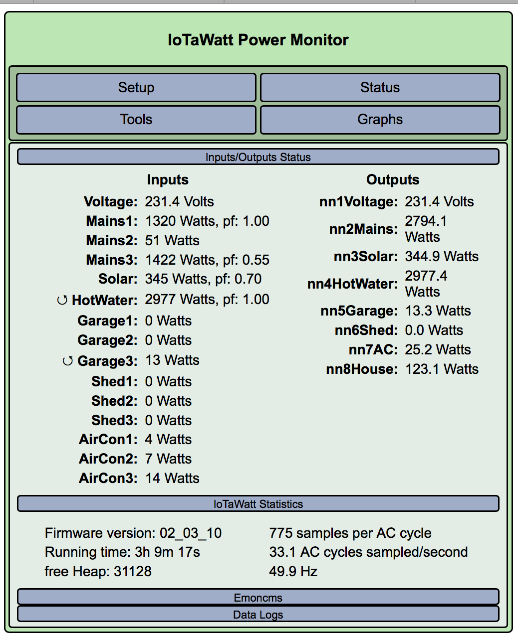
If you could post another status display and your input configuration display over there, I’ll get you started with determining the correct phase assignments. You’re going to need a decent resistive load, like a toaster, electric skillet, or electric space heater.

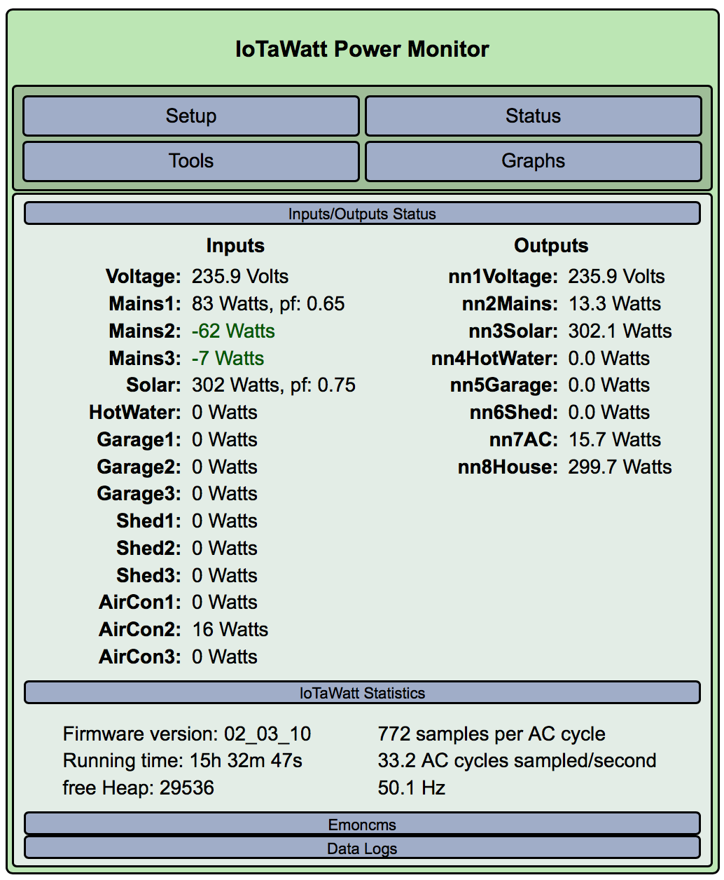
Done. Happy to take advise. Easy to fire up some other loads that make decent numbers. Was considering using old clothes dryer (about 440W), AC in different modes so you can see it works as seperate circuits and the Sauna in the Garage. For the shed I can plug into a single circuit from the board but it also has a seperate circuit to the pool (about 330W).

Again - really appreciate the help and happy to assist/donate where applicable.

I’m afraid your setup isn’t configured for three phase measurements. You are treating everything as if it’s single phase. That will result in completely wrong results for everything on the other two phases. So this may take awhile to straighten out given the time difference.

First, I need to know how well you understand what three phase is. It’s not something I expect most people to know or understand, but I need to understand at what level to approach assisting you. There is a pretty good description of what three phase power is in this OEM Learn Chapter. The first part that explains the concept is what’s important. The second half where they talk about their solutions isn’t really applicable to IoTaWatt, so don’t fret if that bogs down. You should also read through the configuring derived in the IotaWatt WiKi.

The first order of business will be to check that box at the bottom of the input config screen “Enable Derived Three-Phase”. When you do that, all of the inputs will show a new attribute - phase. You will need to figure out and tell the IoTaWatt which of the phases A, B or C is used for each circuit. Further complicating this will be the possibility that CTs are not oriented correctly (backward).

Of the three phases, phase A is the known quantity because that’s the phase the VT is connected to, and the voltage/phase reference of the other two is “derived” from that. But all of the circuits on phase A work exactly as they would in a single phase environment, so we want to identify that. To do that, connect a substantial resistance load to the same circuit as the VT and note which of your mains increases when you switch it on. That will be phase A. The main should increase by very close to the amount of power that the appliance is rated.

I’m afraid your setup isn’t configured for three phase measurements. You are treating everything as if it’s single phase. That will result in completely wrong results for everything on the other two phases. So this may take awhile to straighten out given the time difference.
First, I need to know how well you understand what three phase is. It’s not something I expect most people to know or understand, but I need to understand at what level to approach assisting you. There is a pretty good description of what three phase power is in this OEM Learn Chapter. The first part that explains the concept is what’s important. The second half where they talk about their solutions isn’t really applicable to IoTaWatt, so don’t fret if that bogs down. You should also read through the configuring derived in the IotaWatt WiKi.

I will read the material however at this time I was indeed treating it as single phases as that is what I believe I have - 3 seperate circuits coming into the property and different devices attached to those. EG they are never combined for a high voltage/amperage piece of kit but feed devices that draw 20A/220V from seperate circuits (eg Aircon/Sauna). I was wrong in my monitoring approach
UPDATE: Great links. I can see that we need some tweaking in order to get this read correctly.

The first order of business will be to check that box at the bottom of the input config screen “Enable Derived Three-Phase”. When you do that, all of the inputs will show a new attribute - phase. You will need to figure out and tell the IoTaWatt which of the phases A, B or C is used for each circuit. Further complicating this will be the possibility that CTs are not oriented correctly (backward).

When we configured the units we checked that we enabled loads and then checked that we were only getting positive. Eg if it was showing as negative we reversed the CT orientation.

For the derived 3 phase, I believe I understand what you want: (please confirm)
-turn it on
-mark the mains as A/B/C
-put a load on a circuit and see which of the mains circuits spikes and mark accordingly?

EDITED: Update on Monitor/Referenced Links

I have started below: EG The Hot Water: (I will do the others when it goes off and I can generate a controlled load)

That may well be the case, nevertheless, those three separate circuits are not in phase, so using the VT on phase A as a reference to determine power on phses B and C will not work properly. That’s what the derived three-phase algorithms do, they derive a voltage/phase reference for phase B and C by numerically shifting the phase of the reference on phase A. There are quite a few IoTaWatt in Australia, and all those I’ve seen are like that.

That isn’t always accurate. It works great with single phase because the 180° shift makes it obvious. With three phase, a circuit can be 120° or 240°(-120°) out of phase to start with, and then if the CT is reversed, it can be 60°, 180° or 300° out of phase. That can produce some misleading results when the power factor of the appliance being observed is fairly low to begin with (already shifted a lot). That’s why I’m asking for an unambiguous resistance appliance for reference. It has no inherent shift (pf 1.00).

That’s why I’m asking for an unambiguous resistance appliance for reference. It has no inherent shift (pf 1.00)

I am suggesting the clothes dryer but have also got the wires hair blow dryer which is a little more portable.
Let me know what you want me to to do.

OK, so the hot water is designated as phase C, yet the pf is .49. The cosine of 120° is .50, so that’s no doubt not on phase C. While it is running, try changing the phase to A and B. When you get it right, the pf will be .99 or 1.00 and the watts should go to about 3000.
If the “reversed” symbol precedes the input when it is 3000 watts, you can safely assume that it is.
When we know which it is, you may be able to sort it out using the color of the conductors, if the electrician who wired it observed a convention.

OK, let’s see what happens when you start the clothes dryer.

Ummm. Just realised that internal house stuff may not be super useful as I don’t have any monitoring on house circuits. (We ran out of inputs on the IotaWatt.)

I did fire it up and screenshot attached but its attached to house. Will also keep an eye on the hot water as it kicks in. I had picked circuit C as that was the “Mains” input I could see that was supplying the load.

EG Dryer appears to be on Mains1/A

EDIT:
As an FYI, the shed monitors go to a seperate older board. It appears to have lighting, power and pool pump hanging of the circuits for it. Ditto for the garage so it will be possible to generate a load and observe. The house ultimately is less of an issue for me but I can move CTs around across the circuits if you need me to try this for phase troubleshooting

Let me know at whatever level works for you. I can organise an Electrician if needed or will stop you when over my head.

Could you plug the hair dryer into the same outlet as the VT and see how the mains change. It’s important to determine that.

Are are 2 screen shots.

Hair Dryer ON

Hair Dryer OFF

Hair Dryer ON (With no Hotwater)

EDIT
Added Hair Dryer ON with no Hotwater ON as I realised it may affect trouble shooting
Hair Dryer is labelled as 1800watts but…

It looks as if the VT is on phase A. Not sure about the 1800 watts vs ~1300, but pf 1.00 indicates the correct phase.

Im curious why the hot water is now 3000watts with pf 1.00. Did you change that to phase B?

I agree that VT is on Phase A.

I changed Hot Water to Phase B as when it kicked in, Mains B spiked in conjunction so I made assumption it was B.

Let me know what you want me to do next.

I will get you photos of the boards I am dealing with tomorrow when I have some light.
One has been updated a little and 2 are pretty old.

It does appear to be on B. From the previous experiment it also seems to be on main3, so I think main3 should also be phase B and by elimination, main2 should probably be phase C.

With the mains properly labeled, you may be able to determine which main is associated with each of the remaining circuits, and assign them to the same phase as their associated main. This is where you may find that the various feeds to shed, garage, and AC are color coded by phase.

Of particular interest will be the solar, because the main associated with that should have “allow negative values” checked so that it can properly track exported power.

For the benefit of anyone reading this to understand the logic, I misspoke here. What I meant to say was that it looks like the VT is on main1.

With this derived reference method, the VT is always on phase A by definition. That is to say that the definition of phase A is the phase where the VT is located.

The phases had been assigned to the mains somewhat arbitrarily as a starting point, and as it happens, main1 was assigned phase A and the plug for the VT is on the main1 circuit.

Note that main2 and main3 were also arbitrarily assigned to phases B and C respectively, but those turned out to be incorrect and it was actually C and B respectively.

The notion of numbered circuits 1, 2, 3 and phases labeled A, B, and C are arbitrary labels, and does not necessarily indicate any ordinal relationship between circuit and phase. That must be determined by observation, or tracing circuits, or some other method of deduction.

Once determined, it is possible to sort it out and establish that ordinal relationship by moving the CTs. In this case that would involve swapping the CTs in inputs 2 and 3, and reassigning the phases 2=B, 3=C.

Or not, you can just leave it as it is recognizing that phase is just a new attribute of the circuit and doesn’t need to have any ordinal relationship to the names.

I have updated Main3 to Phase B and Main2 to Phase C as suggested. This then gave me the following results which may mean I need to reverse the CTs?

Solar was already set to allow negative and we have some sun so we should be able to get some readings soon. (Picture below of Solar generation as of 9.44 this morning. I think there is something else I need to tweak with solar as it thinks I am making 44 watts or so during the night so I think it might be reading a little high at present)

I will post some pictures of the board as I am assuming that

With the mains properly labeled

you mean with the configuration we have done vs any clues left by the installing electrician???

UPDATE: Added a picture with some solar happening

Here are some photos of the electrical boards I have inherited on this property. Once I get a handle on things and some spare cash, I may upgrade but at present its a low priority due to cost.

Originally built in 1974? and the Garage and Shed boards are still original.
I believe that the solar was installed in 2007 and included a refresh to the main board.

The wiring is still pretty much original behind the boards. (eg red/black/green which is old for australia and no color coding for the phases).
CTs are all installed behind the main board which hinges and is an external metal box (typical for Australian)

Main Board

Garage
(workshop power/lights/sauna/fridges/etc)

Shed
(only the pool is connected these days - no boiler/compressor)