DIY system - firmware questions

PS: Watching the serial output, the last few messages say:

MDNS responder started for hostname IotaWatt
LLMNR responder started for hostname IotaWatt
timeSync: service started.
statService: started.
Updater: service started. Auto-update class is NONE
9/16/20 08:18:49z timeSync: RTC initalized to NTP time
9/16/20 08:18:49z Real Time Clock battery is low.

(The last message is perfectly understandable, given there is no RTC! :smile:)

I was hoping to have my monitoring system ready for tomorrow’s solar system installation, but sadly that’s not going to happen now.

Is no-one able to offer me a clue as to why I can’t connect with the IoTaWatt software? The code is just too complex to quickly understand – it would take me a month of Sundays to get my head around it!

I can ping the NodeMCU’s IP address on my network (though it’s pretty slow – round trip time average = 34ms), and I’ve tried accessing iotawatt.local with the Windows firewall turned off, but still the same error as reported above.

Daniel

You are connected. This is the part of DIY where you start to do it yourself.

index.html resides on the SD card, so make sure your SD card is correctly formatted and has the files from the SD directory of the github repo.

Bob, I understand where you’re coming from, and thank you for your past guidance, which has been immensely helpful to me.

Regards,
Daniel

@ToadWarrior,
Many thanks for your hint. After copying the “SD” directory files to my SD root, I am now getting the expected Menu screen for the energy monitor.

Great timing too, as the guys are right now installing my solar system, so I’ll now be able to install my monitor alongside the inverter!

I really appreciate your help!

Regards,
Daniel

Can anyone help me with channel mappings for IoTaWatt firmware?

The default firmware appears to be for v4.4 hardware rather than v5.0, but either way it’s not clear what the mappings are for the firmware’s ‘Chanel 0’ … ‘Channel 14’ vs the U1 and U2 ADC channels.

Do the firmware ‘channels’ correspond to the Jn connector reference numbers on the v4.4 schematic, or is it some other scheme?

Thanks in advance…

Daniel

They all use the same firmware. Beginning with late hardware 4.8 and continuing through 5.0 at present, IoTaWatt manufactured units have version and other hardware variables encoded into the EEPROM. At present, specifically, the board version and reference shunt voltage. The values of the burden resistors are also initialized in a SPIFFS file.

If your board does not have this EEPROM information, it is assumed to be a 4.8 board and the burden is assumed to be 24 ohms. There were a number of late 4.8 boards manufactured with 20 Ohm burdens and all version 5 boards have 20 Ohm burdens.

The default reference shunt voltage is 2.5Volts, but that can also be changed with an entry in the device section of the config.txt file, as can the burden values.

The mapping of input number to internal address is the same for all versions, but that too can be changed in the config.txt file. The external channel numbers run from 0-14. The internal address is 0-15 where the high order bit is the ADC (0 or 1) and the low order three bits are the ADC channel. ADC 1 has the voltage ref on channel 0 so the mapping from external channel to internal address skips over that using the formula:

address = channel + (channel/8)

0=0
1=1
2=2
.
.
7=7
8=9
9=10
.
.
14=15

See the modules setup.cpp, getconfig.cpp and iotaInputChannel.h for details.

Bob,

Thanks for all this info – it was most helpful! I realised after study of this info and your schematic that I had got my ADCs back-to-front. As I’m only using five ADC inputs (2V5 Vref, VT1, CT1–3), I connected (on my PCB) all those to what I thought was the ‘first’ ADC (based on your schematic 'ADC1–17 notation), but turns out to be the ‘second’ ADC. This allows me to omit the other ADC IC and its clamp diodes, and save a few cents! (Though my PCB allows for the fitting of the other ADC and diodes and connectors, for anyone wanting more.)

So when I finally worked out where my VT1 was connected, I went to the ‘Calibrate’ screen and was most pleased to see that the default factor (20) gave me an exact mains voltage reading, according to my Tektronix (true-RMS) DMM. Then I went about configuring my CTs, having also worked out where they were.

Needless to say, because the firmware is accessing the ‘second’ ADC all the time, the NodeMCU’s blue LED is lit continuously!

But some time later, I looked at the Status screen, and noticed that the mains voltage was low:
Status20200923
(it’s usually over 240V).
So I went back to the Inputs config screen to recheck the Calibrate (VT) screen, and found it now reporting ridiculously low voltages, changing rapidly and ranging from over 30 to –1!
VT_cal20200923

So I’m a little lost, being unable to reconcile the Status and Calibrate screens and their very different (but both wrong) values.

Are you able to offer any suggestions on where I should start looking?

Regards,
Daniel

Sorry, I have no idea.

OK, I carefully checked my hardware, and found a dry solder joint on one of the VT divider resistors. After fixing that, I now get stable and accurate mains voltage display in the Status screen:

But the frequency is totally wrong!

Additionally, though I currently have only two of the intended three CTs connected, the one (from the inverter output) that had current through it this afternoon (I could measure a small AC voltage across its burden) still shows zero for its power in the status screen.

My ADC connection scheme is different from ‘standard’. I have VT connected to ADC1.4, and the three CTs connected to ADC1.1, .2 and .3. The 2V5 reference is on ADC1.0.

So I’m pretty sure I’ve assigned the correct channels:


but still no reading from the Inverter channel.

I know it shouldn’t, but I’m wondering if the firmware is perhaps making an assumption that the principal VT will be on ADC0.0?

Still perplexed,
Daniel

While awaiting my Rev.1 PCBs, I’m just looking at the firmware. It’s very complex, in a language (C++) I haven’t learnt, and calls on Arduino libraries, which are often poorly written/documented. So I have little hope of understanding it in detail.

But I’d just like to sound out some minor changes with anyone who has a reasonable understanding of the firmware…

Bob’s original code has a block in Setup.cpp that is headed:
// Initialize the EEprom for testing
// Ordinarily to be done in manufacturing.
and is commented out (line-by-line).

I’m assuming that for a newly-manufactured unit, he uncomments that block to initialise desired values in EEPROM. So presumably the following would work, just by changing the #if constant to 1 for first run, and 0 thereafter (apologies if the ‘blockquote’ formatting has mucked-up my indenting!)?

// Initialize the EEprom for testing

EEPROM.begin(EEsize);
#if 0 // Ordinarily to be done in manufacturing (change this constant to 1)
memcpy(EE->id, “IoTaWatt”, 8);
EE->EEversion = 0;
EE->deviceMajorVersion = 5;
EE->deviceMinorVersion = 0;
EE->mfgDate = 0;
EE->mfgLot = 0;
EE->mfgBurden = 20;
EE->mfgRefVolts = 2500;

for(int i=0; i < EEsize; i++)
{
EEPROM.write(i,EEbytes[i]);
}
EEPROM.end();
#else
for(int i=0; i < EEsize; i++)
{
EEbytes[i] = EEPROM.read(i);
}

if( ! memcmp(EE->id, “IoTaWatt”, 8))
{
if(EE->EEversion > 0)
{
log(“EEPROM unrecognized version %d”, EE->EEversion);
}
else
{
deviceMajorVersion = EE->deviceMajorVersion;
deviceMinorVersion = EE->deviceMinorVersion;
VrefVolts = (float)EE->mfgRefVolts / 1000.0;
}
}
#endif
EEPROM.end();

But it would seem (to me) easier to just do something like this:

// Initialize the EEprom for testing

EEPROM.begin(EEsize);

for(int i=0; i < EEsize; i++)
{
EEbytes[i] = EEPROM.read(i);
}

if (!memcmp(EE->id, “IoTaWatt”, 8))
{ // EEPROM is initialised
if(EE->EEversion > 0)
{
log(“EEPROM unrecognized version %d”, EE->EEversion);
}
else
{
deviceMajorVersion = EE->deviceMajorVersion;
deviceMinorVersion = EE->deviceMinorVersion;
VrefVolts = (float)EE->mfgRefVolts / 1000.0;
}
}
else
{ // not initialised, so initialise it
memcpy(EE->id, “IoTaWatt”, 8);
EE->EEversion = 0;
EE->deviceMajorVersion = 5;
EE->deviceMinorVersion = 0;
EE->mfgDate = 0;
EE->mfgLot = 0;
EE->mfgBurden = 20;
EE->mfgRefVolts = 2500;

  for(int i=0; i < EEsize; i++)
  {
  	EEPROM.write(i,EEbytes[i]);
  }

}
EEPROM.end();

Or have I totally misunderstood the EEPROM usage and initialisation?

Daniel

Just resurrecting an earlier thread. I have built Iotawatt as a homebrew V5 based on the published gerbers and as I am not at all proficient at compiling, is there a stand-alone program that will write the necessary parameters into the EEProm that is detailed in the Setup.cpp file so that I can get it up and running? I have looked online (Github etc) and there doesn’t appear to be such a program, but I thought there may be a requirement to write directly to an 8266 EEprom under certain circumstances? I have found programs to read EEprom (which I have tried, but nothing about stand-alone programs to write.
Alternatively is there a compiled file available, which includes the basic information forEEprom setup? Any comments appreciated.

Not aware of any such program. As you have discovered, uncommenting the code in setup is the provided method.

Short of that, you don’t need to compile the IoTaWatt firmware with VScode and platformIO. You could use any of the tutorials to setup the Arduino IDE and make a program with only a setup() function that runs that commented code.

Hi Bob,
That is exactly the path I was going down after finding the learning curve to use Platform IO a bit steep and using the Arduino IDE to compile the firmware was an alternative, so thanks for confirming this was the right way to go.
I have now tried compiling the following code using the IDE and I get a message " error: ‘EEPROM’ does not name a type".

#include “IotaWatt.h”

//*************************************** Process the EEPROM ****************************************

EEprom* EE = new EEprom;

uint8_t* EEbytes = (uint8_t*) EE;

size_t EEsize = sizeof(EEprom);

// Initialize the EEprom for testing.

// Ordinarily this is done in manufacturing but homegrown users

// can activate this code to initialize their EEprom.

EEPROM.begin();

memcpy(EE->id, “IoTaWatt”, 8);

EE->EEversion = 0;

EE->deviceMajorVersion = 5;

EE->deviceMinorVersion = 0;

EE->mfgDate = 0;

EE->mfgLot = 0;

EE->mfgBurden = 20;

EE->mfgRefVolts = 2500;

for(int i=0; i<20; i++){

EEPROM.write(i,EEbytes[i]);

}

// EEPROM.end();

EEPROM.begin(EEsize);

for(int i=0; i<EEsize; i++){

EEbytes[i] = EEPROM.read(i);

}

if( ! memcmp(EE->id, “IoTaWatt”, 8)){

if(EE->EEversion > 0){

log("EEPROM unrecognized version %d", EE->EEversion);

} else {

deviceMajorVersion = EE->deviceMajorVersion;

deviceMinorVersion  = EE->deviceMinorVersion;

VrefVolts = (float)EE->mfgRefVolts / 1000.0;

}

}

EEPROM.end();

delete EE;

EE = nullptr;

}

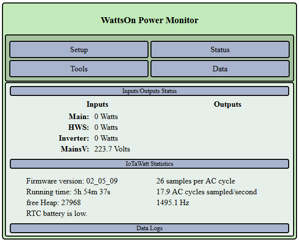
I do appreciate that this is a “homebrew version” and I need to go down a learning path myself, (and I am certainly learning), but any pointers on what the actual EEPROM type issue is, would be appreciated as I am very keen to get the board operational, as the information it will provide is very important for a planned house switchboard upgrade in the near future.

OK, I didn’t realize that you cannot program in c++.

You should be able to use the firmware from Github without initializing the EEprom. The only two things I can see are:

  • The device will assume it is a V4 IoTaWatt and add some phase shift to the channel 0 VT.
  • The voltage reference will be the default 2.5V.

If you are using a different voltage reference, you can add the following parameter to the config.txt json device object, changing the 2.5 to whatever you are using.

"refvolts" : 2.5

I have no experience on C++ but with a little guidance, I can probably work my way through it, hence the reason for querying the error " ‘EEPROM’ does not name a type". I have the board up and running except I can’t see a VT voltage displayed (shows 0 volts), however I can see the correct AC frequency of 50hz and it varies by 0.1 hz, so I assume it is working OK. I have an approved VT (Jaycar Powertech MP-3027) which I know provides an 11 V output to the VT plug.

The reason I have been focusing on EEprom initialization is I made the correct or incorrect assumption that a value (2500) was needed in the mfgRefVolts to get a voltage reading in the Input/Output table for the VT. (I did do as you suggested and added a line to the config.txt file to indicate that I have a 2.5V reference, which I have, but it made no difference).
Can you confirm whether this is the case and if I am incorrect, I will investigate whether I have a board fault? .

The value stored in the EEprom is in mV, so 2500 is correct for a 2.5V reference shunt. If the EEprom is not initialized, the firmware will default to 2.5 Volts. That is stored in the float value VrefVolts.