9 vs 9.5, not definitive until you get to about 100kWh elapsed.
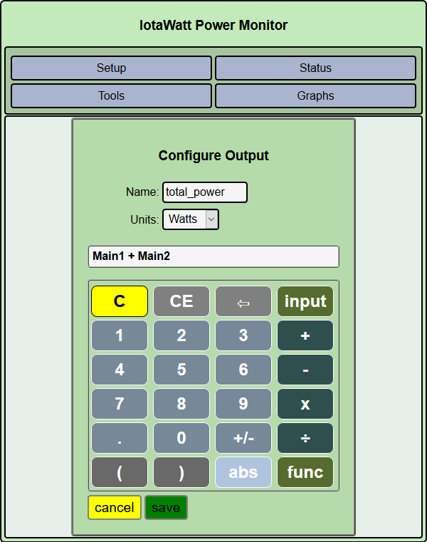
In the config app, click setup then outputs. click add.
click save.
Now total_power will appear in the status display and also will be a menu pick in graph in both the power and energy tabs. It is computed on the fly, so it will work for the historic data you have been plotting.
After you do that, yopu can get creative and make outputs for your solar production and actual usage.
Meter says 27263
I’ll post another graph same as above after I get more kwh used…
With mains combined and both inverter wires combined, then it does not show any negative numbers on the graph…so guess I have to wait and see if ecompany meter charges for negative power flow by checking their meter to what iotawatt says I’m using after I accumulate some kwh.
Seems like this will work for my needs…Main reason I got the iotawatt was to be able to find out if my 240v single phase inverters are overfeeding therefore backfeeding into the grid due to the 240v single phase inverters supplying the split phase panel
1 Like
I do not have a net meter that would subtract backfeed coming from inverters from your total home usage…also I do not have a net meter that will keep track of power feeding into the grid…nor do I have the old style spinning disk meters (sometimes digital) that u could run backwards…I just have a stupid meter that if it sees current flowing in any direction it charges for it…I think they started using these to stop ppl from putting a magnet on the meter to make the meter read less than actual usage
There are standards that a revenue grade meter must adhere to. Those standards address functionality as well as calibration. I am doubtful that a meter could comply with those standards if it charges for exported power. Is there some official statement about this?
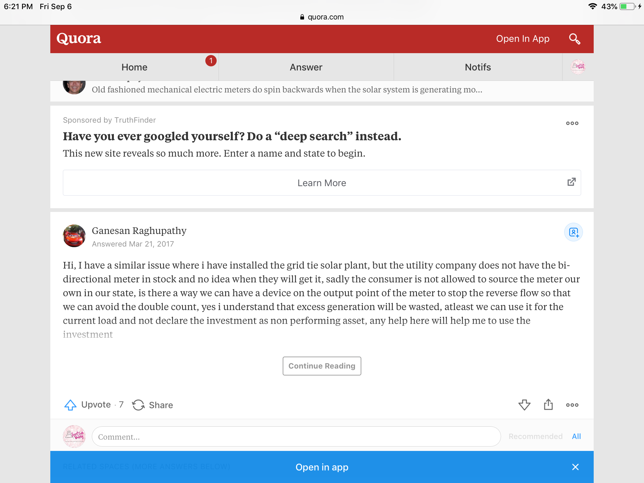
Well not official documentation but this is what I found in a quick search
to avoid the above they made inverters with limiters (just produce what loads are at any moment) so I shouldn’t have to worry about feeding into grid but I’m using single phase inverters to supply a split phase panel…which seems to work great when I have high loads and inverters can’t supply all of the loads, the graphs show no feeding into the grid at these times…but when inverters can supply all of the loads it appears to be different when looking at the graphs on Iotawatt…usually when inverters can cover all of the loads the loads are 120v loads and it seems (considering iotawatt graphs) that when these 120v loads are unbalanced by more than like 80w (amount inverters let grid supply) the inverter overfeeds one leg (minus the 80ish watts) and underfeeds the other leg by the same amount. I’m hoping that’s not due to each of the inverters wires supplying the same power thru each wire to each leg loads that are unbalanced…I’m hoping that since the inverters are 240v single phase that reading the power output with iotawatt at 120v, each wire is not giving a true inverter output due to 240v power the inverters are supplying pushing and pulling differently than 120v power…maybe I shoulda used a 240v reference…?
Example: 400w load on main1 and a 100w load on main2 tells the inverter to produce 500w and going by what the iotawatt says the inverter puts out 250w thru each wire therefore underfeeding main1 by 150w and overfeeding main2 150w minus the 80w the inverters let the grid supply to not overfeed supposedly. That example (what the iotawatt atm is saying is happening) is what I hope isn’t happening.
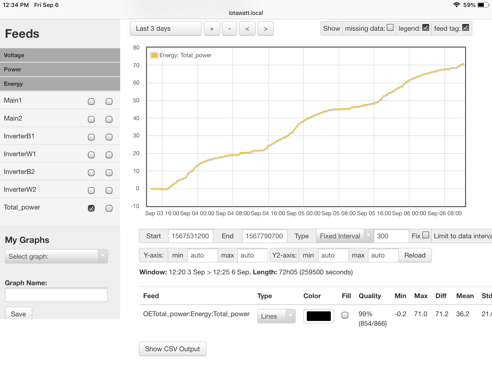
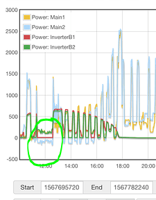
OK, sounds like you have crowdsourced the problem. The only thing I know for sure is how IoTaWatt works. If your CTs and VTs are oriented correctly, it will give you the kWh that would be measured in a typical net-metered system. If your inverter limiters are working as expected, the net power from the grid will not go negative. So in spite of the imbalance and apparent export on one leg, the IoTaWatt should match your meter over time. So lets take a look after you use a couple hundred kWh. If it’s significantly off, then maybe devise some experiments to see what’s going on. According to the plot above, the net total for the mains never went below 22.4 watts. You should have “allow negative values” on for the mains.
Yes it says it never went below 22 but that’s when the negative is taken off the positive (by adding them both in one output) therefore implying that there wasn’t a negative-backfeed amount at the time of the load imbalance and implying that the other leg wasn’t underfed.
I do have negative values on for both legs and iotawatt shows negative values on separate legs when the aren’t added into one output.
You’re getting lost in the weeds here. Yes, I understand that one leg indicates negative power and the other positive, but the net is positive. So as long as that is the case, my thesis is that the IoTaWatt will match the meter, and that’s what you are actually using i.e. no excess billing for the negative legs. I believe the meter measures net energy.
I’d like to clarify that I did not get a net meter from the electric company like most ppl do when they get grid tie inverters so they can oversupply their loads… instead I got limiting inverters to not oversupply my loads…
I believe my actual question has something to do with the waveform that my 240v inverter supplies it’s power, which I think is different than what the individual 120v waveforms of my main panel are…so do the two 120v references I’m using also read the waveform of each leg?..if they do then I’m using those waveforms-volt references for my reference for the inverters supply so couldn’t that cause the graph to show over and underfeed…maybe the over and underfeed isn’t actually happening but using the 2 waveform references that I am using (waveform of individual 120v circuits) for the cts on the inverter wires makes the graph read it wrong? So thats why I’m asking if maybe I needed to use a 240v reference instead for the inverters cts
I got that.
They read the voltage waveform. The CTs read the current waveform.
Without a doubt the two VT setup complicates the picture and has set the stage for all kinds of questions and also opened up more possibilities for incorrect orientation of the extra CTs on the inverters. I can only assume they are correct.
Seems to me that the whole two 120V and 240V reference effort is red-herring. You seemed to go that way out of concern for a few Watts being misread. This whole dual limiting inverters environment and inappropriate metering problem was never mentioned.
Yes, I do think that it would be simpler to use a single VT to study your inverter/meter situation. But I don’t see any reason why you can’t use your channel 0 120V VT for that, just like practically all of the other solar installs out there that are getting good numbers.
The only difference between a 120V on one leg, and a 240V reference, is a potential small voltage difference if the loads are imbalanced. They will be exactly in phase.
I mentioned the limiting inverters 14 days ago before I purchased the iotawatt. Not that I’m unhappy with the iotawatt…I’m just trying to figure out if the inverters are actually backfeeding to grid or not…I’m thinking the inverters power they produce might be getting read wrong, reading the right amount of power but the inverters would push and pull out of each wire and keep switching the push and pull between the wires…or maybe idk, maybe the inverters are just over and underfeeding like the iotawatt says they are…could the voltage waveform be not properly mating with the current waveform in regards to the inverters somehow?
Do the inverters have a neutral wire?
Yes they have a black-hot, a neutral-hot and a ground…I suppose the neutral isn’t used as hot in some countries. During times when I have more loads than inverters can handle (a lot of 240v load) the inverters do not show backfeed or underfeed
let me ask it a different way. In your panel, there is a bussbar with white wires connected to it. That is your neutral. Is there a wire running from that bussbar to your inverter? I’m not interested in a ground wire that would be bare or green.
No the neutral is not going to neutral in main panel…the neutral-white goes to the opposite side of the 240v breaker…the black goes to other side of the same breaker…the neutral is not bonded to the ground inside the inverter
FCOk, that’s not a neutral, that’s the other hot. It is common to connect two wire loads to a panel with black/white wires. Three wire uses black/red/white.
But I digress. My point is that there is a single circuit to your inverter. The current in each wire is exactly the same. The inverter cannot physically deliver different current to the black and white wires.
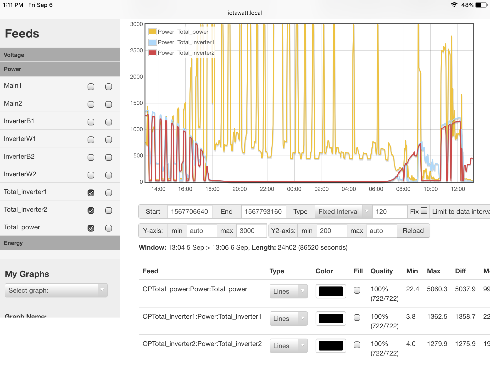
So now let’s imagine your load is out of balance by 1000 Watts. How does the inverter supply 1000 Watts to negate that load? I think the answer is that it pushes 1000 Watts into its 240V circuit. That reduces the 1000W 120V load to 500W, and drives the other leg negative 500W, resulting in a net mains load of 0 (I’m ignoring the 80W bias you described). If I’m right about this, adding the InverterW2 to this plot would lay right over Main1 and InverterB2 in the circled area.
Like your inverter, meters do not typically have a neutral conductor. They see everything as 240V and measure the sum of the two legs - at least in an all positive world.
It may be that your meter doesn’t net that negative and positive, rather adding the absolute value of each leg. I don’t know. Anything goes with an electronic meter. I’m pretty sure a mechanical would net to zero, but then again it would also run backwards. As someone who has essentially designed and built an electronic meter, it occurs to me that the easiest way for the meter to net the two legs is to electrically connect the CTs on each leg in parallel with one reversed. integrating that current signal with the 240V voltage signal should yield the net power. Depending on the algorithms used, they could lose the sign in the integration or later, but the point is that the sign would be used in netting the current on the two legs. My money would be on that, and I don’t see the point of the limiting inverters if it’s not.
So the IoTaWatt is essentially a meter that truly nets the two legs. What I keep saying is that you need to let it run long enough to determine if your meter works the same.
UPDATE: edited details of inverter output above from 500W to 1000W
In that graph both inverters output are displayed…B stands for the black wire from each inverter…B2 stands for the black wire for second inverter…also in the above graph where u circled the second inverter isn’t supplying power at all due to the first inverter (B1 and W1) thinking it’s supplying of of the loads
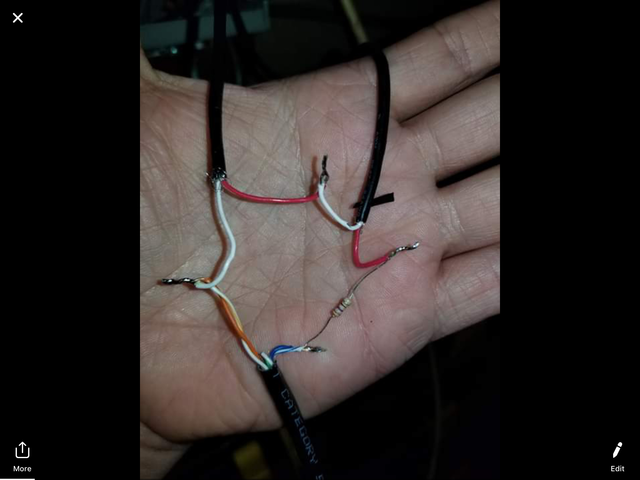
Ok so the cts connected to inverters and mains are wired in series and one is reversed here’s a pic
I get that. I was talking about the white wire from Inverter2. Your Inverter1 is not producing any power in the cited period. Inverter2, which seems to be the primary inverter, is showing half the power needed to match the load because the Black wire is being interpreted at 120V. The White wire is the other half of the story and should show the remaining power needed to reach equilibrium. Humor me. I deliberately included the start and end unix times.
InverterW1 should be zero.