Loss of one VT causes all logging to stop

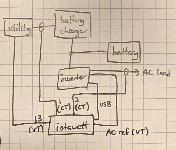
I have an IotaWatt set up as part of a homemade double conversion UPS and redundant DC power supply. (Battery charger, battery, and inverter are all in parallel with some loads connected to the inverter and some loads powered by DC in the middle.) I have two VTs: one connected to input (utility) power and one connected to output (inverter) power. The 9V AC REF port is connected to inverter power (because it is redundant), and the utility VT is connected to port 13. I am pulling metrics from IotaWatt using custom monitoring software via the HTTP API.

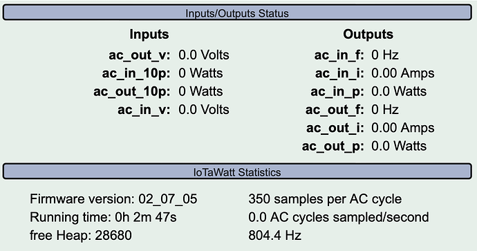
Normally, this setup works great, but if I cut input power, the loss of power to that VT causes IotaWatt to slowly (but not instantly) grind to an almost complete halt. It works okay for about two minutes, reporting input power as zero volts, but then it starts returning nulls for everything, even if I query only metrics associated with the other, still-powered VT. Eventually, everything goes to zero in the IotaWatt interface, and it even loses the ability to display data about the logs in the “Data Logs” section of its status page, which becomes totally empty. Rebooting the device does nothing.

Oddly, under “IotaWatt Statistics,” the device displays some crazy frequency, like 800 or 1300 Hz while in this condition, even though its primary VT is still powered and fine.

This condition persists until I restore power to the VT. If I then look at the graph interface, I see no data points at all during the period when the single VT was unpowered.

Is there any way to fix or work around this issue? I was hoping I could monitor both sources of AC independently, but the device seems to be freaking out totally at the loss of only one.
Is the answer essentially Power outages and data recording - #2 by overeasy ?

I would need a line diagram of your setup to understand this.

I may have just accidentally discovered the answer myself. While performing maintenance on the system, I shut down the VT connected to AC REF while leaving powered the other VT connected to 13. This is the opposite of what I did earlier. During this period, IotaWatt seems to have worked just fine.

While I have read that IotaWatt needs a VT for clock purposes, I thought that the VT connected to AC REF was the one providing this critical clock, but in my case, it appears that port 13 is serving that function. Can you confirm that it’s supposed to work this way?

If so, then the answer to my question appears to be that I should swap the ports to which the two VTs are connected.

By this diagram, the only thing the utility powers is the battery charger, and all of the loads are powered by the inverter all of the time. I suspect that is not the case.

What I said is what I am doing: Double conversion UPS on Wikipedia

If you don’t believe my drawing, you could also imagine having a house running on a generator with one VT connected to the main panel (and thus to the generator) and another VT connected always to utility power (which might be unpowered, or it might come back, but if it came back, the cycle of the generator with respect to the utility would be unsynchronized, and the phase between them could be anything).

I checked out the source code to have a look myself. The firmware appears to be of good quality and organization. I can see how what you’ve said about the AC cycle’s being required for timing and correct operation is true.

What is not clear from my inspection is how the system operates if there exist two or more VTs and one is powered while another is unpowered. It looks as if the code should set the system’s frequency based on whatever VTs are powered (be it one or more than one), but obviously I am missing something, for what is actually happening appears to be more subtle than that.

Can you tell me how multiple VTs (which may be powered or unpowered) affect the frequency computation and thus the timing of the main sampling loop? It seems that the higher-numbered VT may be more important, but I don’t see in the code why that would be.

It’s not that I don’t believe you, it’s that the behavior that you are describing does not comport with the drawing.

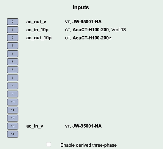
Can I see your inputs setup display please?

That looks like single phase 120V. Not familiar with anywhere that is used. Can you verify?

Yes, I am only working with a single phase of 120 V. I don’t have the CTs in a panel but rather just attached to line splitters. I’m not monitoring a panel but just a single system on a single 120 V circuit.

I am in the US and have standard split-phase electrical service, but I am not monitoring the house as a whole, just this one system.

So when you cut input power and the system “slowly grinds to a halt” and stops logging.

  • Are you sure there is voltage to the inverter output VT?

  • Does it continue to show 120V after you cut input power?

  • If so, at what point does it go to zero?

What I expect to happen is that the input13 voltage would go to zero and the input zero CT would go to zero, but the inverter output would continue under battery and the input0 voltage would remain 120V and the load CT would continue to show power.

To start off with your questions:

Yes, the inverter output VT is always powered. Yes, it shows voltage if I cut input power IF measurement doesn’t freeze up, which it often does. It does not go to zero.

I triple checked that the VTs are connected in the way I said, and yes, they are. You can also tell that is true because the output VT will always say about 120.4 V, which is what my inverter outputs, whereas the input VT will fluctuate over the course of the day as utility voltage moves up and down.

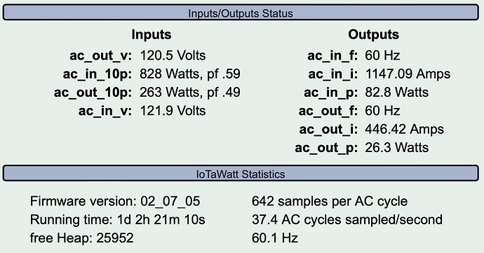
Today when I flip the utility/input VT on and off, I see a couple of different things happen. Here is a snapshot from before I do anything.

(FYI, in case these details matter when you’re looking at these images, the inputs ac_in_10p and ac_out_10p are from CTs wrapped around 10x line splitters, so the measured currents are 10x the actual current. Also, the outputs ac_in_i and ac_out_i are 1000x the actual current, i.e. they are in milliamps. Also, there is a large difference between input and output power due to other loads (about 41 watts) powered directly from DC that IotaWatt doesn’t know about and isn’t measuring.)

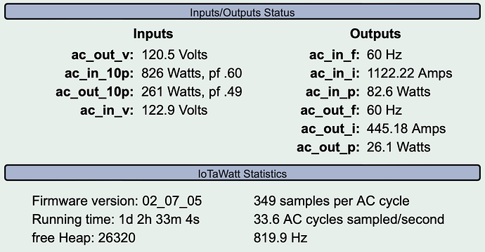
Then, I flip a switch to turn off the ac_in_v VT. Usually, the following happens:

The input/output numbers are frozen and are not updating. As you can see from the samples per AC cycle and Hz numbers, however, something has gone wrong.

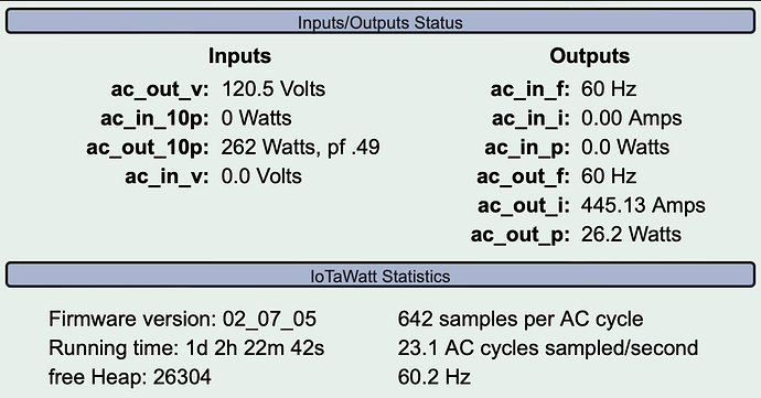
One time, however, the following happened, and the system was stable for several minutes:

I’ve previously seen it run in this state for a minute or two before failing into the state of my second image, but despite my having flipped the input VT on and off several times today, I haven’t seen that happen today. I note that AC cycles sampled is lower in this image than in normal operation. I don’t know if that’s significant. I guess IotaWatt is spending more time searching around and trying to synchronize with the unpowered VT?

I should mention that these two AC sources are not synchronized at all and in fact run at slightly different frequencies. At this moment, via the web API, the input VT says 60.01 Hz but the output VT says 60.17 Hz. I have verified the output frequency with a multimeter; the inverter just runs a little fast. I don’t know if that matters to you; it doesn’t seem to matter to IotaWatt when both VTs are powered.

You show a display with voltage shown on both CTs and go on to explain that the display is frozen.

You show a display with my expected response.

So now I’m confused. When you say you’ve previously seen it run in this state for a minute of two, are you referring to the state immediately above the paragraph that shows it running as I expected with zero on the input VT?
When you say it fails “into the state of my second image” which image do you mean, the frozen image? But you say it hasn’t happened today and the frozen image appears to be taken after the expected image with the input VT zero.

I expect that the unit may freeze and not log of both of the VTs are zero. In the post you asked about, I explain that the unit is expected to stop and restart in the event of a power fail. I think it will keep running if one of the VTs is putting out a 50-60Hz signal, and the reduced cycles sampled is also expected. I should note that half the inputs are active and so sampling at half the rate still results in the remaining inputs being sampled at the same rate as when both VTs were active. Failed samples are not counted.

When it does stop after several minutes, I cannot envision what IoTaWatt mechanism might be responsible for such a time delay. Now that you have explained the experimental nature of your setup, could it be possible that the inverter stops after several minutes?

When I cut power to the input VT, one of three things happens:

(1) IotaWatt runs normally, input VT says 0 V, output VT says 120 V
(2) IotaWatt stops logging, displaying a very high samples per cycle and frequency, and eventually after several minutes, it displays input VT as 0 V, output VT as 0 V (but output VT is still powered)
(3) first (1) happens, and then after a few minutes, (2) happens

I’ve been flipping the input VT off and on repeatedly, and I notice that after several minutes, everything goes to zero.

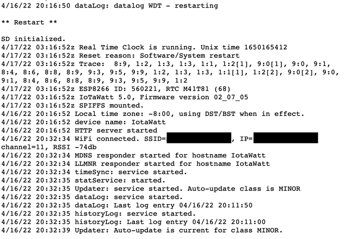
The change to zeroes apparently coincided with a log entry I just noticed. Apparently I have caused the device to reboot:

Note that the startup messages stop at 20:16:52 and resume at 20:32:34. It hung at the 20:16:52 message while the input VT was unpowered. At 20:32:34 I re-powered the input VT.

The inverter is most certainly not losing power. It is connected to a 100-Ah battery, and the inverter is powering my Ethernet switch. If the switch were unpowered, I would not be able to post these messages.

Is there any further debugging info one can get from IotaWatt? The message log is quite terse.

Thanks for taking the time to listen to my issues.

As a diagnostic step, can you delete inputs 1 and 13 (the input VT and CT), and see what happens as you cycle the input power? Does it still freeze and/or degrade?

Yeah, I’m happy to run any tests you would like. I have run the test you requested, as well as two more tests you didn’t ask for. The test you asked for is #2 below.

For all tests, I started with the input VT powered. Then I switched it off. I waited two minutes before calling a result of normal operation due to the fact that sometimes logging stops after a delay. Then I switched the VT back on and ensured the system was functioning normally for a few seconds before continuing. I ran all tests 10 times.

In an earlier post, I mentioned three possible outcomes which I numbered. Below I give them the names of normal (1), immediate stop (2), and delayed stop (3).

Test #1: baseline

Since the same thing doesn’t happen every time, I wanted to quantify how often the logging problem happens before I made any change to the IotaWatt setup.

normal: 4
immediate stop: 6

Test #2: delete inputs 1 and 13

This test was as you requested. Because IotaWatt wasn’t displaying any data from the VT, I couldn’t check that it had resumed normal operation after switching the VT back on, so I instead I simply waited five seconds.

All ten runs were normal.

Test #3: re-add input 13 only (input VT)

normal: 8
immediate stop: 1
delayed stop: 1

With regard to the delayed stop run, as I was watching the data, I saw the frequency number under “IotaWatt Statistics” jump around a bit, from 60 to 85 back to 60 to 150, etc. Logging continued during this period, although my logging software would occasionally get nulls from the web API. But then it went up in the 300-500 range and logging stopped.

Actually I’m interested in knowing if it operates normally for the full two minutes.

Yes, what I meant was I turned off the VT, observed IotaWatt run correctly for two minutes, turned the VT back on, waited five seconds, then began the test again.

All ten runs of test #2 had IotaWatt run correctly for two minutes after the input VT lost power.

1 Like

Ok, now with 1 and 13 defined again, can you setup about six additional inputs with the default ac ref (output). Just use acuCT-H040-50 for model. You don’t need to actually plug in any CTs, they will just read zero. Repeat the test and see what happens.

I can’t reproduce the problem, so these experiments may help sort it out.