The bad news is that I was unable to recreate this on my development unit. The good news is that I am getting similar problems with the stock 02_07_05 firmware. My development firmware has some changes to the sample logic that appear to be insulating it from the problem. I intend to release this firmware relatively soon, so stand by until the next ALPHA release and we will see if it resolves your problem as well.
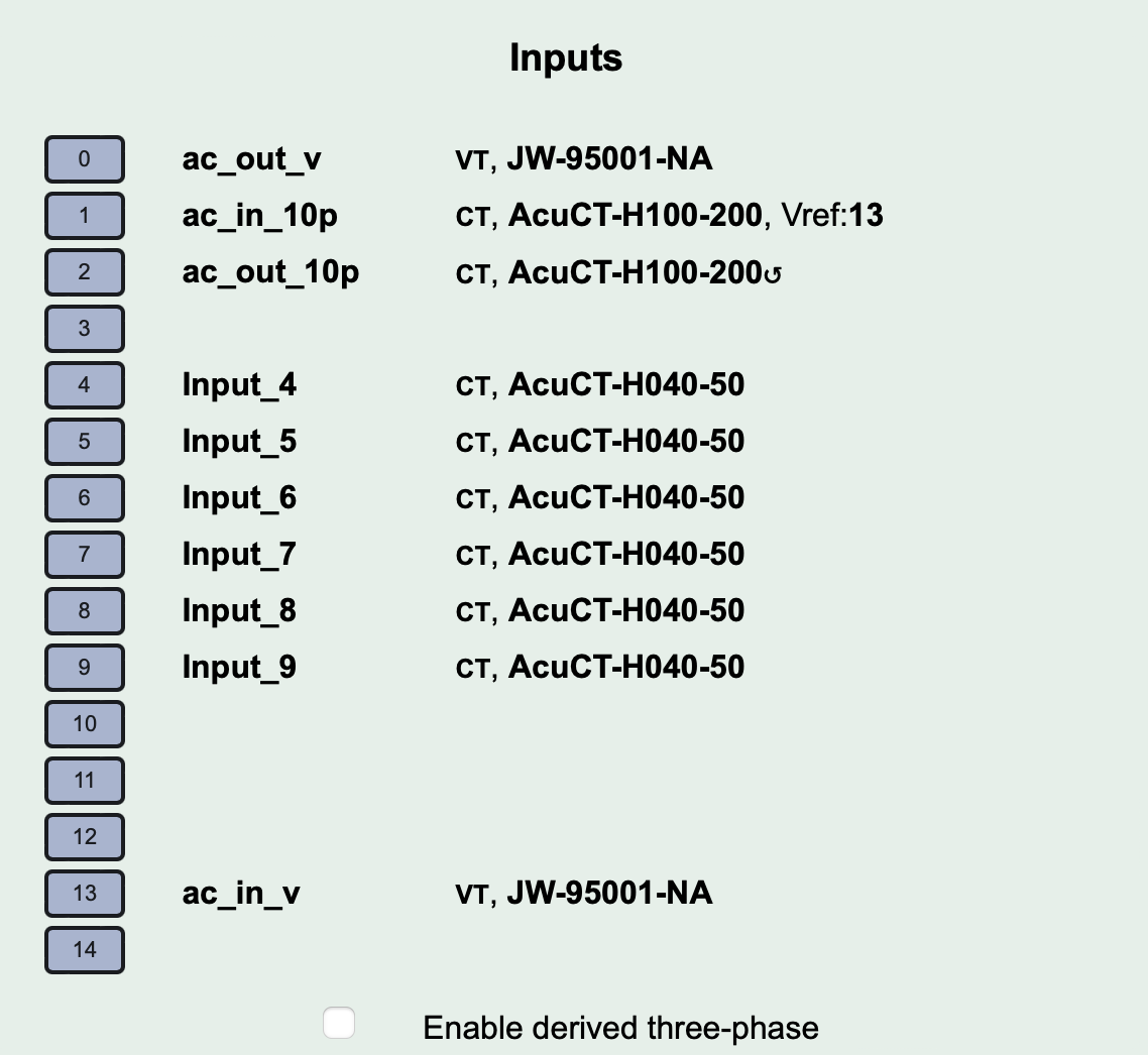
I’ll respond here because you are doing something I’m interested in, which is running an iotawatt on an inverter. But I’m puzzled by the way you are doing it. You have a VT input on channel 13. But the iotawatt expects current on channel 13. (well, technically it expects a voltage that’s a proxy for current, depending on the setup, etc…) If you are just monitoring the utility line to see if it’s up/down, I guess it makes sense. And I suppose that as long as one can supply a proxy voltage or current to an input, an iotawatt can measure and track anything.
But as you mention, the VT input is the one that runs the clock. You have that plugged into the inverter. However, a lot of inverters don’t exactly run at 60hz. By that I don’t mean that they run at 60.123hz or 59.5 or something else. I mean that many of them run with modified sign wave, of which there are a few types. A (crappy) square wave inverter might actually run with a primary frequency of 60hz. But a true-sine inverter is going to run at a much higher frequency which is then modulated to 60hz. When you see 800hz, I suspect you are seeing that frequency. And depending on the load on the inverter, my guess would be that with a heavy load, your output would be cleaner. In other words, with a heavy load, you problem of 800hz would clear up, but with a light load you would be more likely to see it.
Inputs 13 and 14 are for optional three-phase references. I’m (mis?)using only one of those to monitor the utility and my inverter separately.
My inverter runs at about 60.14 Hz according to a nice multimeter. It is a true sine wave inverter, not modified sine wave. The load is indeed light, about 5% of the inverter’s maximum. But as I said in the discussion, the problem only manifests when the utility VT (which is connected to a three-phase reference input, not the main reference input that drives the clock) is disconnected.
Ah, I knew about the three phase, more or less, but not how it was done. I’ll have to read up on that.
Your true sine inverter still has a high frequency component, they all do. How much of it leaks out depends on the design. I might try to duplicate that part of your problem.
There’s only currently an issue when a VT is configured on input 13 but disconnected from power. If it’s connected, everything is fine. If it’s not configured, everything is fine. So at least in my case, the waveform from the inverter seems to be fine for driving the Iotawatt’s clock.
I won’t dispute that there could be a problem with another inverter though, especially as you may know more than I do. (I am a bad, low knowledge electrical engineer.) But out of curiosity, I may hook up my inverter to my oscilloscope to see what it looks like when I have some spare time.
Well, I know a few more things. I put my voltage reference and my usb power supply on my UPS. You need to know that it’s NOT a double conversion UPS. That is, the output is utility power unless the power goes off. When the power goes off, it switches to the internal inverter. Just your basic, but inexpensive, UPS.
I then put a heating load on one of my circuits. Everything looked normal. I then pulled the plug on the UPS. So now the reference voltage is derived from the UPS. And of course, the frequency as well. When I do this, the power consumed by the heater starts to jump all over the place. Or at least it looks like that. If I plug the UPS back in, everything returns to normal. This behavior is exactly what I expected. By running the “clock” on the iotawatt at a different frequency, it make it appear as though there is a phase difference between the current draw of the heater and the voltage. iotawatt thinks that there is a large (and varying) power factor.
Your case is somewhat different though. (I need to be careful here, or I’m going to look like I’m just making this stuff up. But I’ll speculate a bit.) I think it’s hard to measure different phases completely independently from each other. If you shut off one of the phases, the others tend to bleed over, least in the cases I have seen. Although I don’t think that’s a good description either, as what’s really happening is that three small transformer are connected to the iotawatt in some way to recreate the phases. But I’m not really sure. It seems like some change is taking place with the phase relationships. But really, just guessing.
Is the heater connected directly to utility power, not through the UPS? If so, that’s your problem: you gave Iotawatt only one reference, but your UPS is obviously not synchronized with the utility. If you have multiple sources of power that are not in phase (US split phase, three phase, utility vs inverter, utility vs generator), Iotawatt needs to have a VT for each power source and each CT needs to be associated with the VT corresponding to its supply.
(Iotawatt technically doesn’t require multiple VTs in the normal case of split-phase or three-phase because you can tell it what the situation is and the separate phases are probably pretty close to the 180 or 120 degrees they’re supposed to be and the voltages are probably about equal, and Iotawatt will compute something that is probably pretty close. But Iotawatt can’t make any such educated guess in relation to unsynchronized power sources.)
I’m glad you you keep saying “just guessing” and “speculating” and “making this stuff up” because that is more accurate than the information conveyed. With multiple voltage references you certainly can measure different phases completely independently. There is no “bleeding over” from one phase to the other. The transformers don’t recreate the phases, they simply provide an isolated reference.
The operation of the IoTaWatt is synchronized to the AC cycles because that what it does, measure AC cycles, but the AC cycle is not the clock. The processor runs at 40MHz and uses a millisecond clock for task scheduling. The problem with not having an AC reference is that there is nothing to synchronize to, and it spins it’s wheels. That is fixed in the upcoming release. It was an oversight because it was not anticipated that folks would want to run the unit when there is no power to measure.
When there are multiple AC references, as in three-phase direct reference, it has no problem moving between the various references and synchronizing to each.
Yes, the heater was on the utility power and the iotawatt was on the UPS. That was pretty much the point of the experiment, to prove to myself that they had to be in phase. I suppose it’s sort of obvious with hindsight.
I (mostly) did not see the ~800hz thing. (I did see a single frequency sample stored at ~800hz, but it not cause anything to freeze.)
I think for my purposes, I can just keep running my system from the UPS, since my UPS is normally synced to the line. If the power goes off, it will keep running, but the current will be zero for everything I’m measuring. So it’s still accurate even if the frequency changes. And when the power comes back on, either generator or utility power, the UPS will sync up again. So still accurate.