That equipment is completely foreign to me. The interconnecting wires are not visible and I can’t see where any of the CTs are placed. Not looking for more pictures, just saying I don’t think that will help.
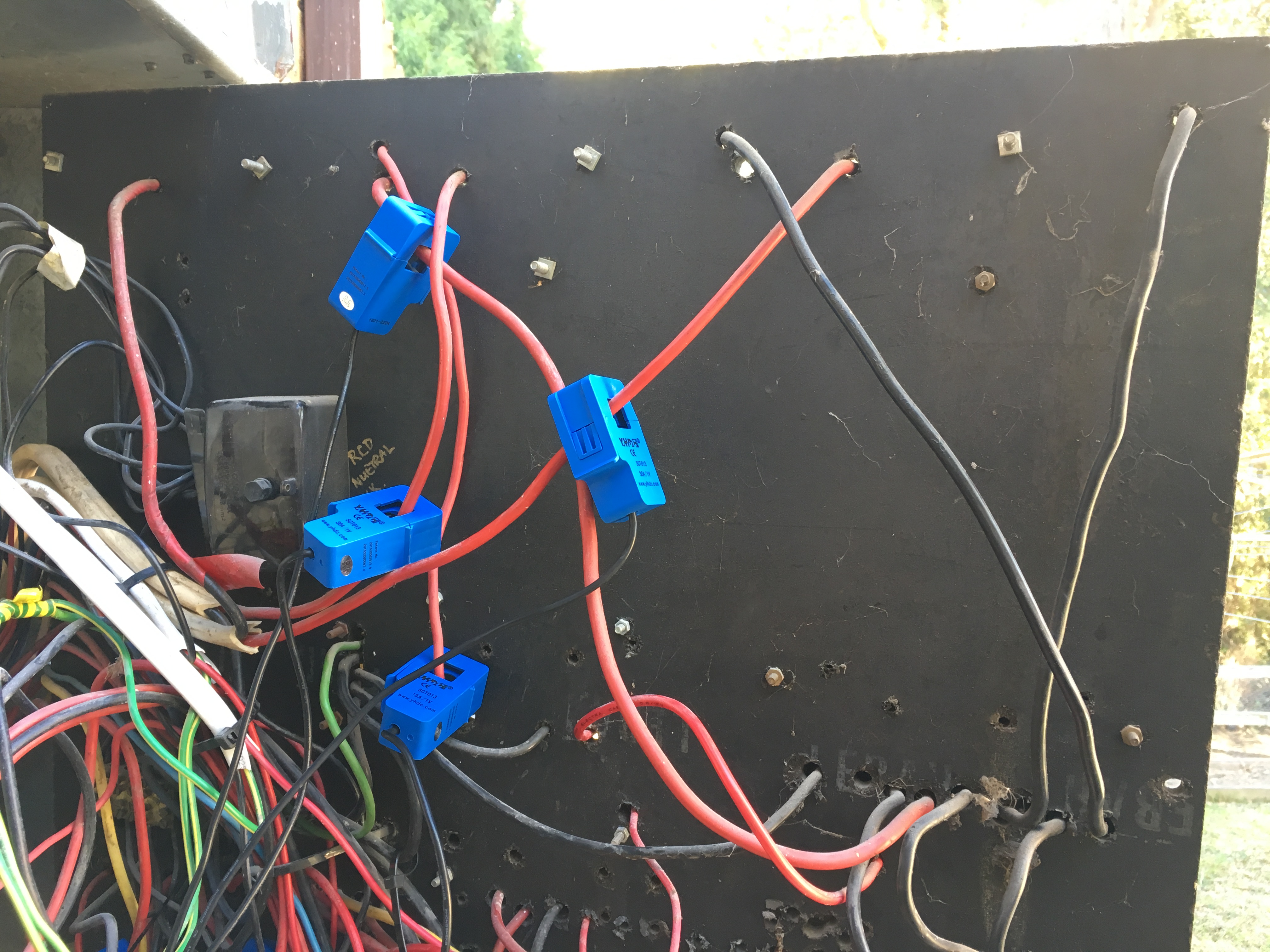
What does seem to be useful is the newer breakers for garage, ac, shed and hw. I don’t see any reason why those should not be wired the same left to right, so if the CTs on those are in order, the phases should correspond the same.
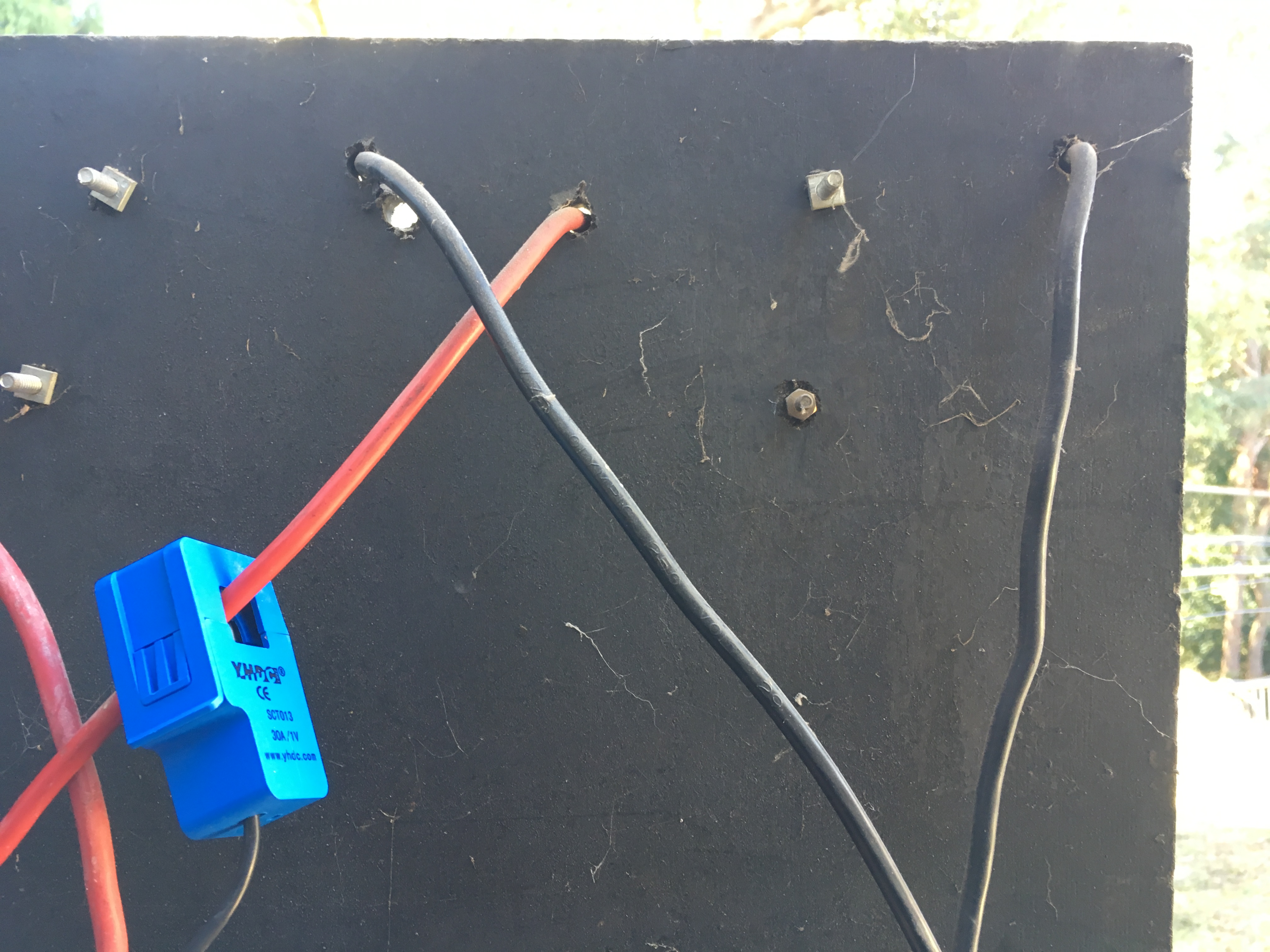
That said, I don’t think we have the mains right yet. The CTs on those incoming cables should all be oriented the same way. Is that the case? I’m thinking it could be that main3 is phase C, and the CT is reversed. There are a lot of combinations of phase and CT orientation, and the effects of erroneous combinations can be similar.
So can you check the orientation of those CTs?
If I were there on the ground, I could probably figure it out in an hour. Halfway around the world, might take a week.
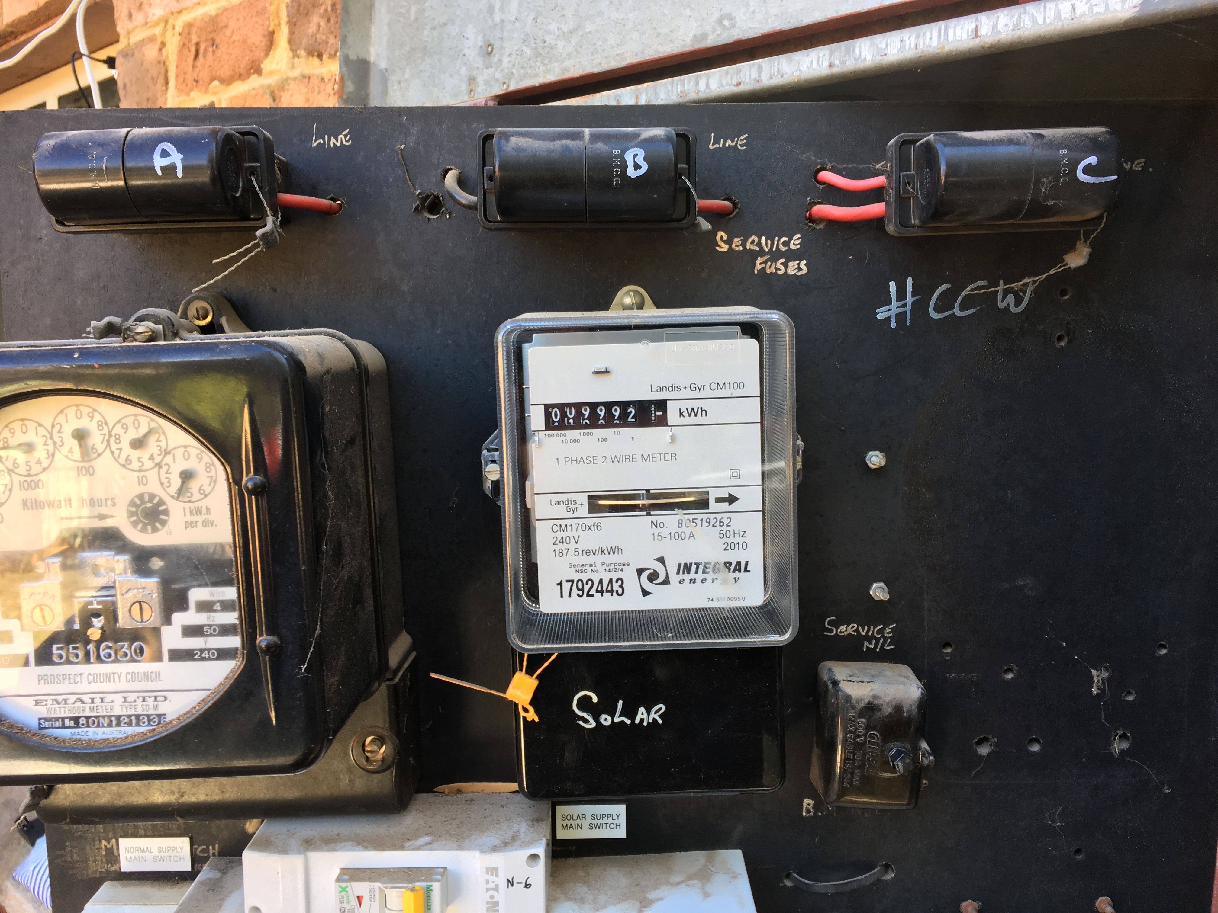
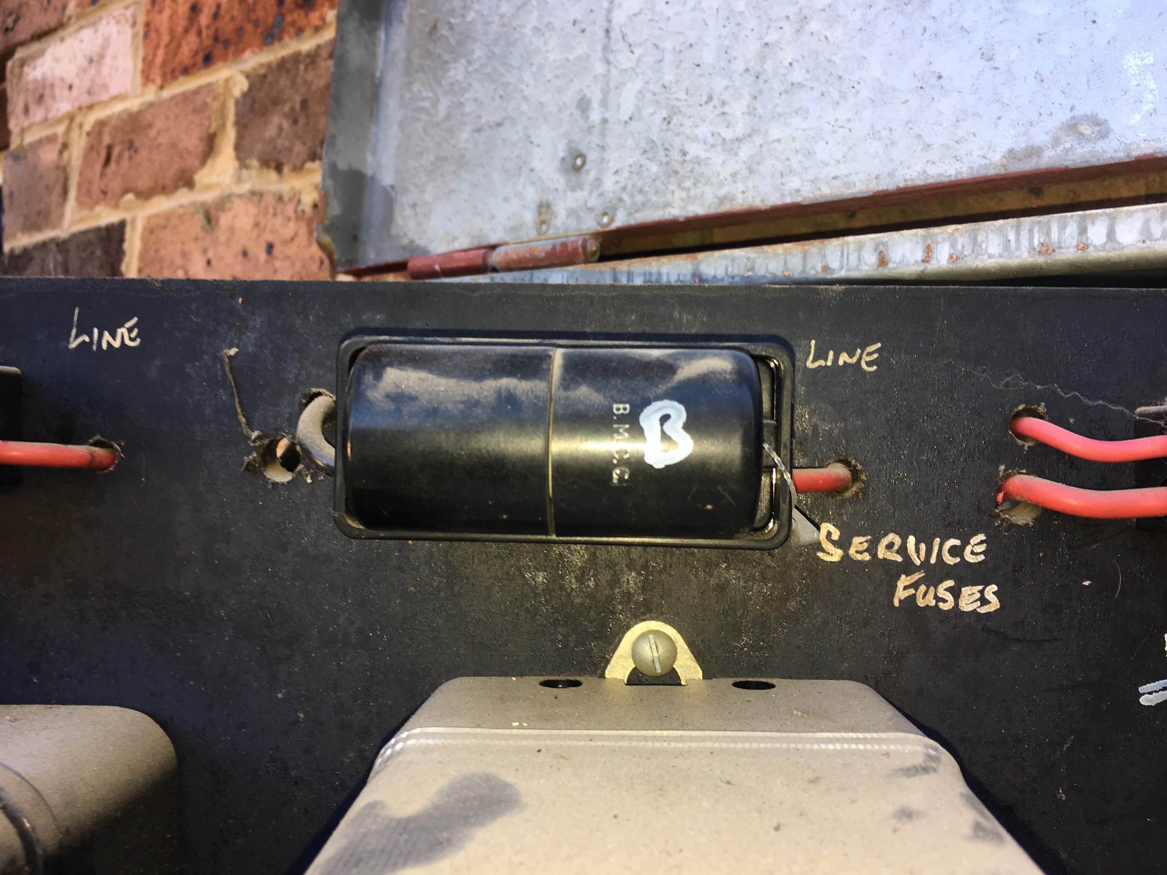
Can’t really see the full picture. Those big fuses have two leads, but it’s not clear which are connected to the supply, and which go to the load. Can you verify that all of the CTs are clamped to the supply, or all are clamped to the load? Because they go one way on the supply side and the other on the load side. The current flows into the hole for the supply, and out of the hole for the load.
We have a fire extinguisher. I will swap the CT for Input2 which is currently mapped to Phase C
it had been around the other way anyways originally and was only swapped as we saw negative… Our mistake. Will try and get a better shot but its tough as the board is mounted and swings and there isn’t much play…
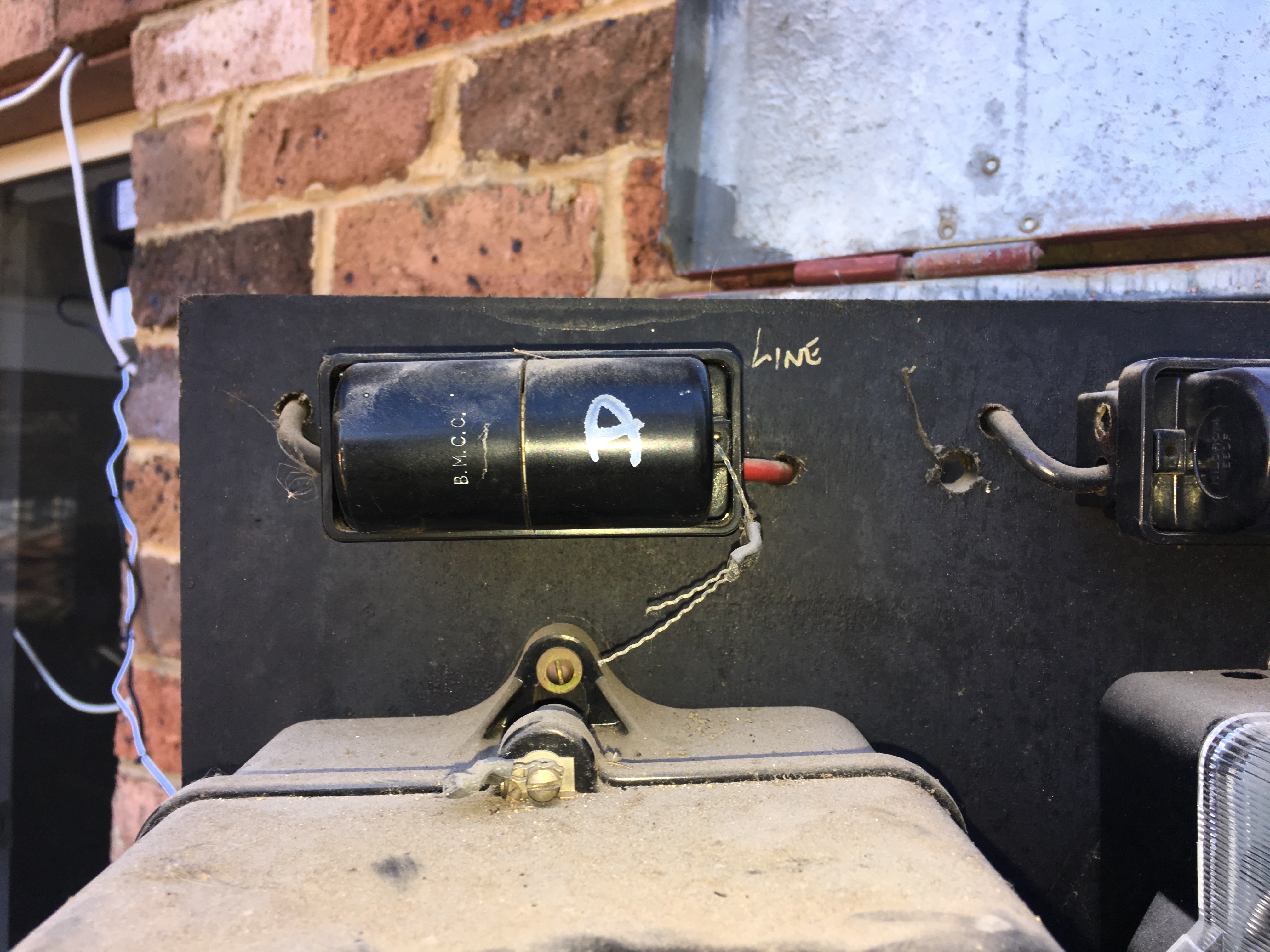
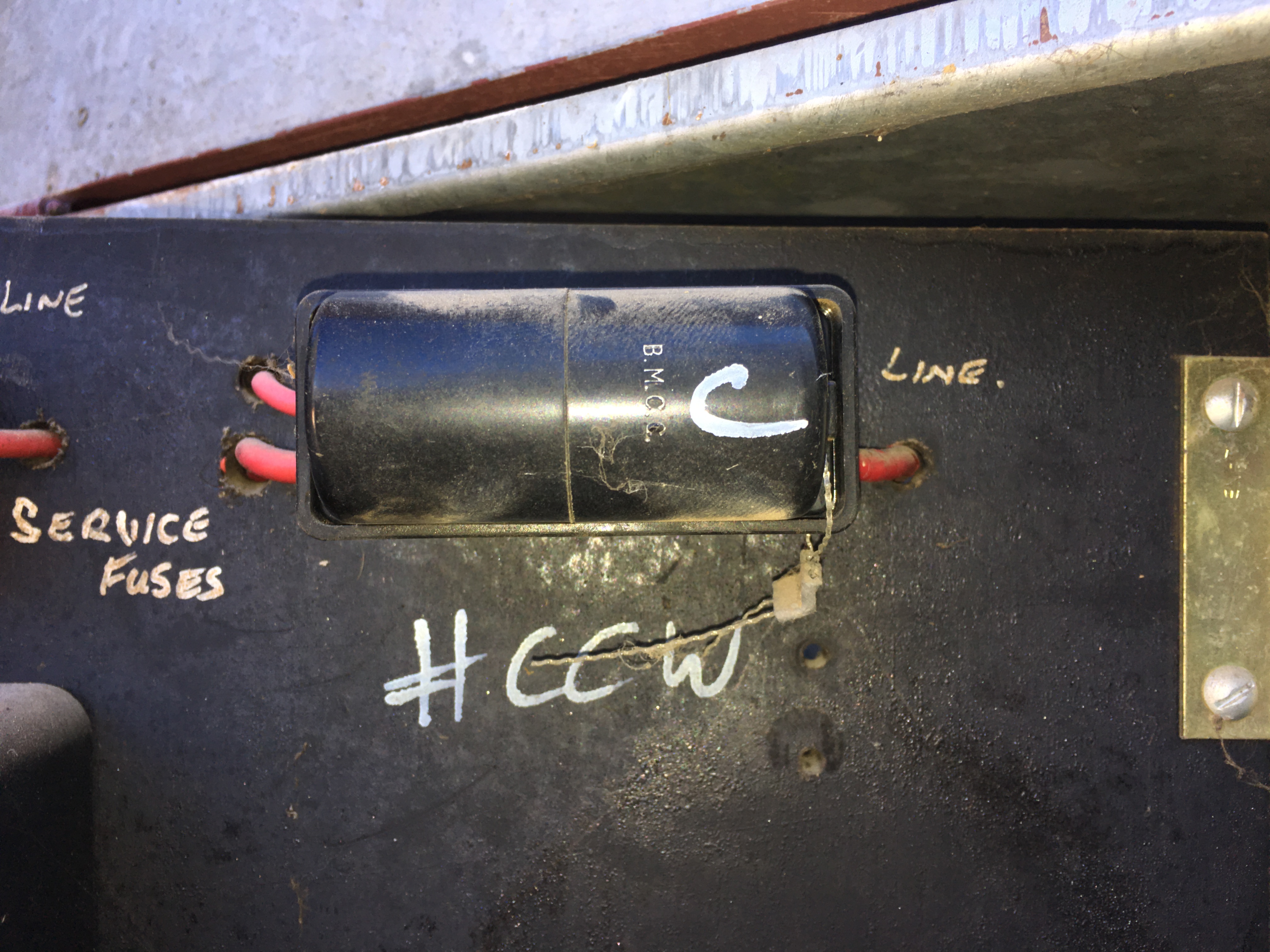
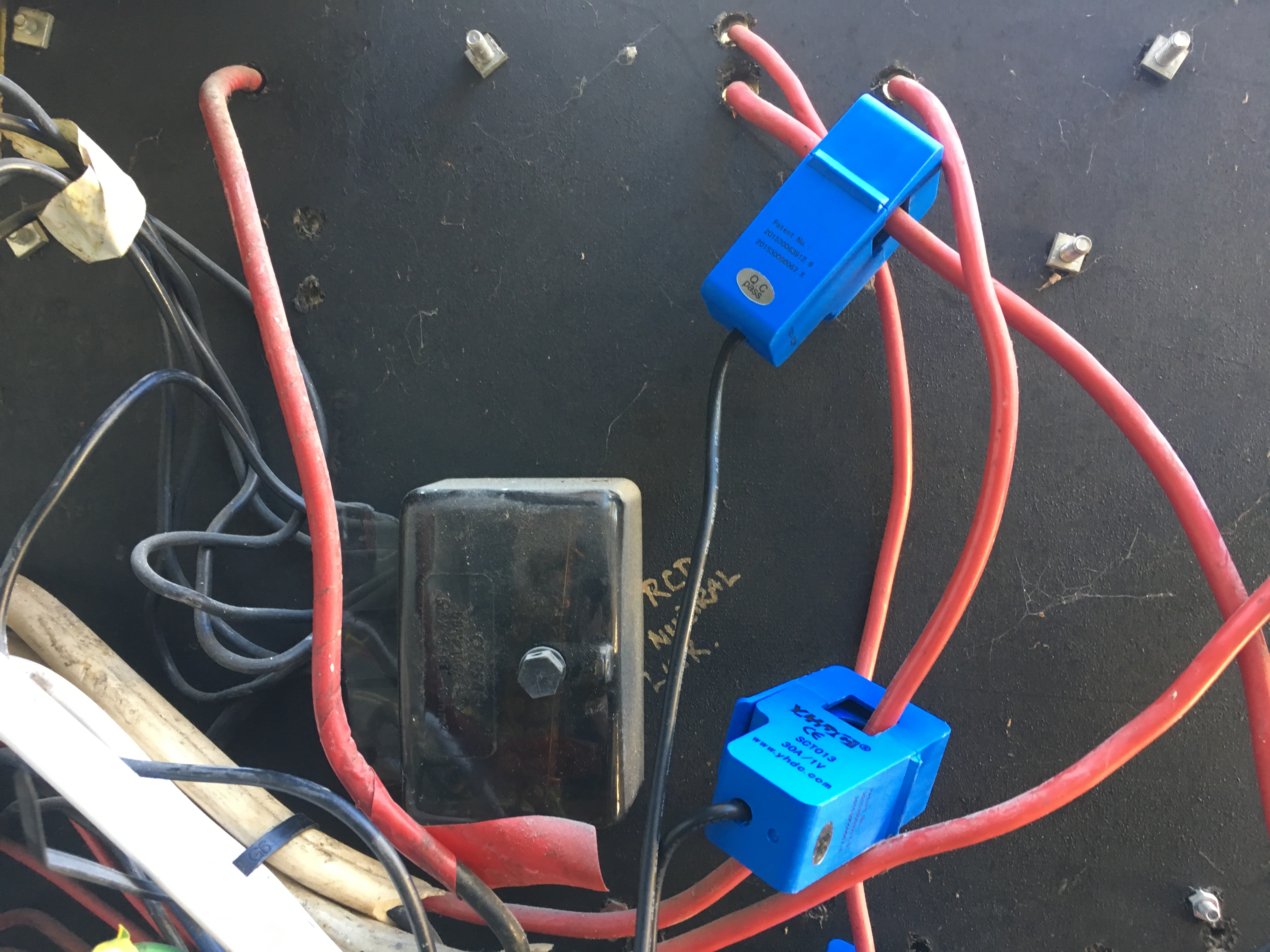
In the pictures above the fuses are marked ‘Line’ side on the right so that would be the supply side. On C phase the CT in this picture is on just one of the load conductors so not measuring all of C phase.
For simplicity it would be best to put all the CTs on the single line side conductor for each phase.
The way these boards is wired is that the supply conductor from the street is first connected to a service fuse that is then connected to a meter and then goes to sub circuits.
In this board there is an original 3 phase meter and when solar was added a single phase meter was added to measure total solar output (gross metering). You are losing a lot of money with a bigger bill by not switching to a net metering arrangement.
I agree re the net metering - just moved in (a few days) and was trying to see how bad the AC was really hurting me.
I have moved the CTs to the single line conductor for each phase and its looking better (I think…) Just need to start getting the other outputs CTs assigned to the right phases.
That said, any advice is appreciated.
Current status (new Raspberry Power Supply and Unifi Wifi network)
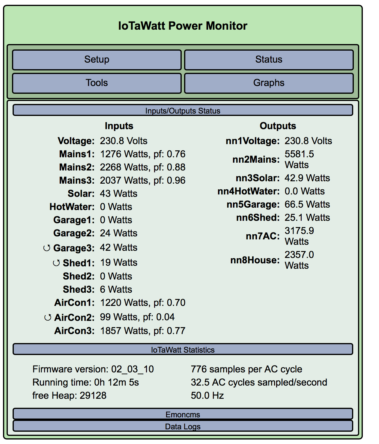
Thanks for looking at this Paul. It’s good to have someone familiar with the local equipment and methods. That explains something I could not reconcile from earlier on. I had pretty definitely determined that the hot water was on main3, yet the total power of main3 was less than the power to the heater.
Still not convinced the mains are assigned to the correct phase, but it does look good.
@bluetardis, do you have an AC voltmeter? If so, you could use it to associate other circuits to the mains. Voltage between phase corresponding circuits will be near zero, while between different phases will be close to 400 volts. Be careful though.
Really appreciate the assistance so far.
I have re read all the doco and took a more detailed look as we have a sunny day today so could get some better pictures.
I am up for any advice as to next steps - but am concentrating on trying to ensure the CTs are correct for Mains inputs and Solar before doing anything else.
Of note is that (and you can see it in the pictures) is the wiring/CT placement for Input Mains “C”.
Also when referencing the PowerBoard I am referencing the inputs as A/B/C as this is what they are labelled and this isn’t necessarily Phase A/B/C, In IotaWatt the following is assigned:
Mains A = Phase A
Mains B = Phase C
Mains C = Phase B
What I have done this morning:
Moved the Mains input C CT.
moved the solar CT to the output on solar (which feeds back to mains input 3) - this is the second, smaller cable from the Phase3 Input C Fuse.
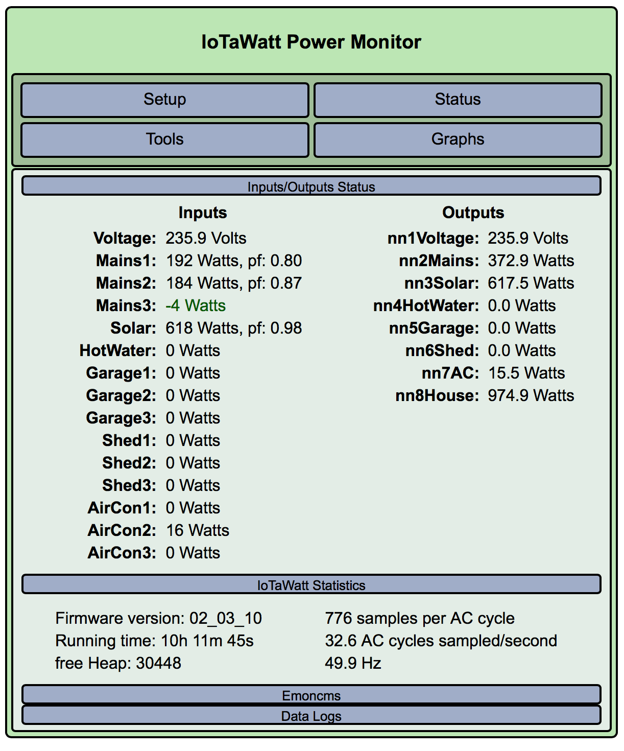
Iotawatt it shows about 620-650W which is close to what the solar unit shows its generating (~680W). ARE THESE NOW IN THE RIGHT SPOT FOR MONITORING??
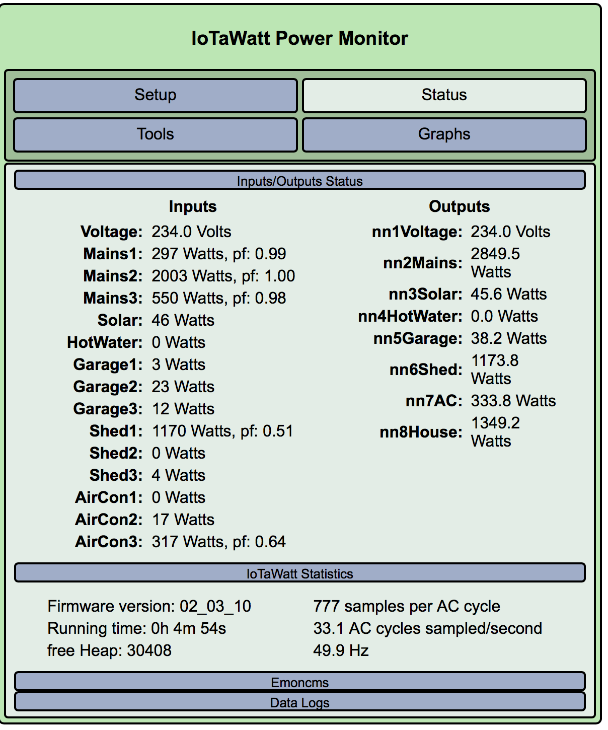
IoTaWatt Status. Its been rock solid since new power supply and new wifi.
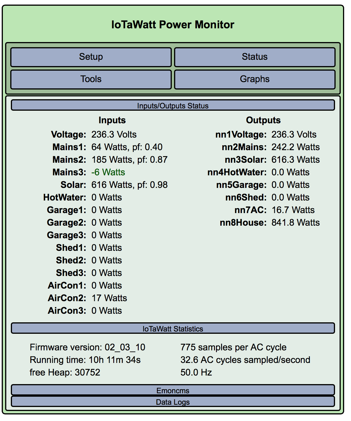
I think the mains/solar is looking better the the pf for Mains1 does move around a bit. Its generally on 0.80 but occasionally drops to 0.40 for a second or so then goes back…
It all looks consistent, except for the low PF, which is possible at that low power.
If I understand what you are saying about the solar connection, it is not going through your mains CTs, so I don’t believe it should be added to your total consumption.
You beat me to it. I had a power failure and lost my edits/post and I need to add some more.
The Line Feed for Mains Input C is split wired between Mains C and Mains A (as marked on the box). As such I moved a few things around and its looking better.
I can also see you put something on a blog which I shall be reading shortly.
Not sure what this means. There can’t be any electrical connection between phases - otherwise it goes bang.
The way the CTs are connected looks correct to measure total load on A,B and C phase and separately the total solar generated. This also aligns to how your meters are connected though your three phase meter records the sum of kwh on A,B and C.
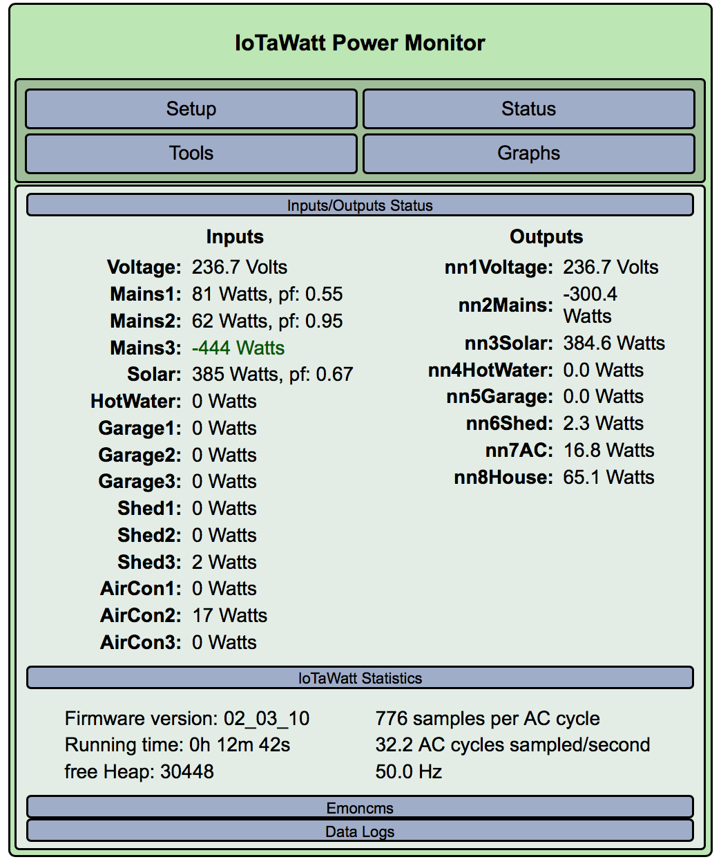
I assume the -6watts on Mains3 is actually 0 watts and there is no load (nothing turned on)at all on this phase.
I need to say that access to behind the meter panel is a job for an electrician as they are legally allowed to do this work and even more importantly they are aware of the dangers and can do this work safely and old boards are even more dangerous.
Hi @Giraffe
The best way to describe it is to say that the wiring I have inherited is kind of interesting.
In the walls and most of the connections are the 70s style coloured cables with some random new ones. There are a few more interesting runs and I will definitely be getting a sparky in to take a look and clean it up. While I am comfortable with single phase there is no way I am touching 3 phase other than hooking up CTs.
There can’t be any electrical connection between phases
If you take a look at the “REAR Mains B and entire board” photo you can see the wiring which corresponds to the “line” on the front for each of the phases. MainA and MainC are split from the feed cable and the electrician has taped the negative/neutral line with Red electrical tape… Interesting approach…
Kind of fits with the rest of the jobs in the property. Good bones but a lot of “half assed” fixes. My favourite so far has been taping the laundry sink drain to the floor with gaff tape.
I assume the -6watts on Mains3 is actually 0 watts.
This does vary as the solar exports to the grid via Mains 3. If the solar is generating and nothing is on it will show 90% of what is generated as a negative.
I really only got the phases corrected yesterday so will monitor for a month and await my first bill with interest.
In time I will upgrade the solar and get a new meter so we can get automatic daily readings remotely and I can see how close everything is but I am pretty impressed with the IotaWatt capability and also the help from the community.
Debating a secondary device so I can get some monitoring up for temperatures across the house so I can see how well/otherwise the air con works.
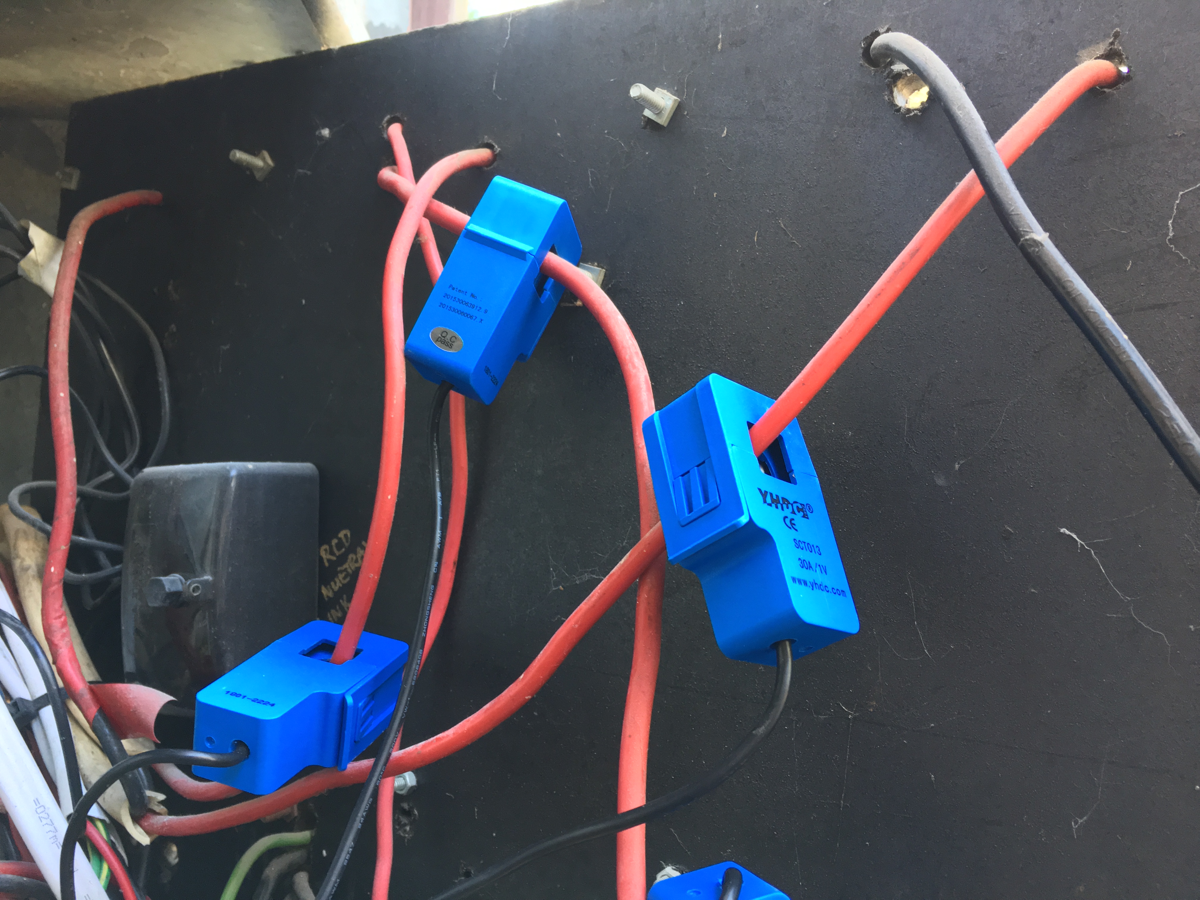
I reckon that the CT for the line on the service fuse marked “C” (unsure which IotaWatt input) should be on the cable that is right on the top left corner (from the back). Fairly sure the CT in the middle / highest one in the picture is missing an “out” (from the fuse) connection. This extra connection, you seem to be measuring from the CT at the bottom.
Another thing might be to mark the input numbers on each of the CT’s. With 14 inputs… BTW - I’ve stolen that Sharpie you gave me the other day.
Cute the way that that “C” Phase is a black cable inside the TPS and then magically becomes a red under the insulation tape. Some el-cheapo sparky decided that rather than source the correct cable from your pole, a pair of single phase cables would do. At least the neutral is black.
So… after some pointers from the forums, I think things are close but need a second set of eyes/hands to complete testing.
I am not 100% sure about the “C” input as there are a few ways it could be used but with current configuration and phase assignment I get close to 1.0pf on that circuit and also an accurate read for solar generation.
There is something odd in the Garage. When I use a load (hair dryer) it shows up in the house not garage feed but I can see it on mains “A”. When I fire up the sauna, I can see it correctly phase assigned and pf of .99 for A/B/C and Mains A/B/C Its possible that there are 4 circuits going to the garage/workshop but that can wait for another day.
That said, nothing would surprise me with this place at the moment.
The other option is getting another iotawatt and another 6 or 8 inputs and measure every damn thing and work it out later. (get the sums right then reduce the feeds going to emoncms). It would be nice to get temperature(s).
Seems to me that it would be more consistent to put the mains CT for C on the line side. In that way, all of the mains are handled the same way. I’d leave the CT on the other output of the C fuse that goes to solar.
What does your meter do when the solar exceeds demand? Does it recognize negative power on the one phase and net that against any consumption on the other 2 phases? I’m thinking that it looks like a mechanical meter and works that way. So maybe there is some kind of ratchet mechanism to stop it from turning backwards. @Giraffe?
I’m curious because if that’s the case - you get net except it won’t go backwards - you would need some kind of min or max function in the scripts to track the meter.
I expect the meter will spin backwards if current flows in the opposite direction. Its just a standard spinning disk meter. However it will never see a negative current as it is dedicated to solar. The three phase meter will never see a negative current as it is dedicated to load.
Of the two wires that leave the C phase service fuse. One will go to the solar meter and then the solar inverter and be dedicated for that purpose - power will only flow out of that wire. The other wire will go to load and power will only flow one way on that wire to the load.
I would be inclined to keep the two CT’s on the two separate wires that leave the fuse. That way you measure total solar generation one CT and total load on the other CT. The total load CT can then be considered as the same as the other two phases - just a load.
This is my best guess based on the pictures.
If there is a need to calculate import or export then it can be calculated from the (load - generation) with the sign changing depending on import or export.
It will work either way, you just need to know what you are measuring and interpret it accordingly.