As previously stated, this is a subset of a larger challenge to measure phase-to-phase circuits in three-phase systems. This case is fairly common. Larger apartment towers bring in three-phase which is great for elevators, common HVAC and lighting, lower commercial spaces, etc. For the residential units two of the three phases are supplied to a sub-panel, appearing to be just like the ubiquitous 120V/240V split-phase. Except it’s not quite the same. Each leg to neutral is 120V, so all the plugs and lights appear to be the same, but the phase-to-phase voltage is only 208V rather than 240V. That’s because the two legs are 120° out of phase rathert than 180°. Most high-voltage equipment sold in North America is rated for both 208V/240V, although heat and/or power output is typically a little less when using 208V.
When the two legs are 180° apart, the high voltage 240V is the same phase as the VT. With these “208V single-phase” panels, the high-voltage is 30° out of phase with the VT on phase A.
Yesterday, we diagnosed this condition and got the mains legs recording correctly using the IoTaWatt derived-reference capability. It is also possible to add another VT (V5 IoTaWatt), and have a direct-reference for the second leg. But this was quick and simple and accurate enough (definitely more accurate than setting up like a common split-phase panel).
One consequence of this type of service is that the power-factors for the mains are meaningless. Part of the power used in each leg is 120V in phase with the voltage reference, and part of it is 208V 30° out of phase. I should probably just suppress the PF display in this case.
The user has also setup some branch circuits using two CTs for each 208V circuit. Unlike 120V/240V panels, this is the only way to do it if there is a neutral wire. In other words, if the appliance is using both 120V and 208V as with the mains. I suspect the dryer in the above example is doing that. You cannot use the split-phase method of passing both conductors through the CT in opposite directions.
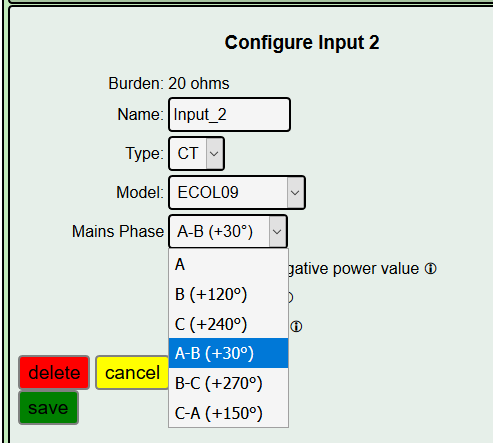
Beyond this residential application with 208V single-phase, the same can happen in a three-phase panel when a single-phase 208V appliance is connected. The difference is that it can be connected to any of the combinations A-B, B-C, C-A, with corresponding phase shift from phase A of 30°, 270° and 150°. So the problem requires a solution to cover all three of these cases.
With the ability to measure the power in a conductor using phase-to-phase voltage (rather than phase-to-neutral), it should be possible to measure delta wired loads in a wye system using two CTs.
I’m moving cautiously into this because if I get it wrong, untangling the user interface changes will be messy. I’m putting out an experimental configuration utility that allows specifying phase-to-phase reference. The other part of it is that the shifted voltage reference must be multiplied by the square root of three (1.732) in order to reflect the correct voltage. While this change will set that value in the config file, it won’t be used without changes to a subsequent firmware release.
These changes should also work in other three-phase environments such as NA industrial 277V/480V systems and Euro-Australia 230V/400V systems.