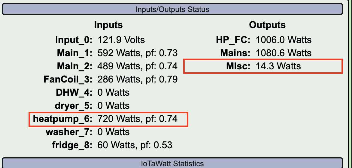
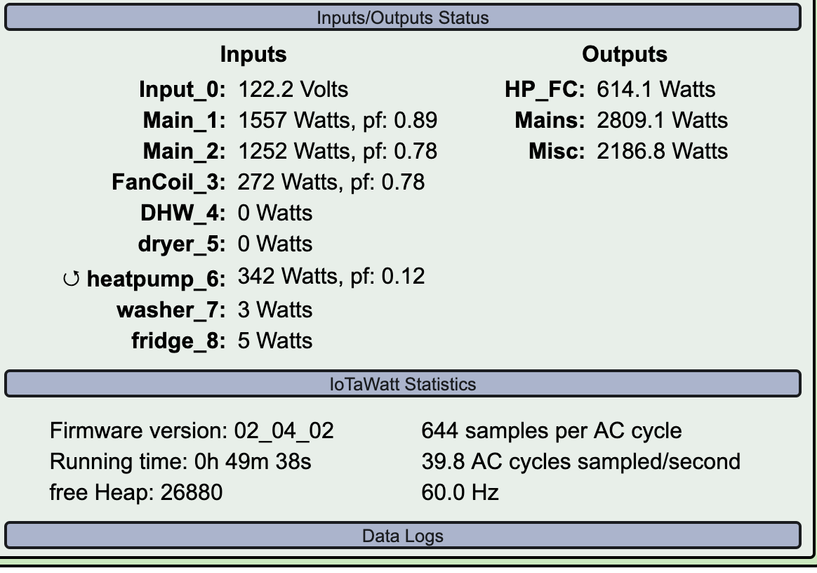
I’m hoping you can help me troubleshoot an issue with the Output Tool. I created an ‘Output’ to report all miscellaneous power from unmonitored circuits, but this value is sometimes negative and at other times it is abnormally low.
I’ve also noticed my heatpump circuit is shown as reversed when in idle mode, but the reverse symbol disappears when the heat pump compressor is turned active. I’m not sure if these issues are related. Below are some screenshots for reference.
Unfortunately, as tools go, IoTaWatt is a ruler rather than a micrometer. There is room for improvement here, but your expectations may be overly optimistic.
First thing I would recommend is that you reconcile the mains with your meter to insure you are in the 1% or so ballpark. To do this plot the mains output in the energy tab. The max reading is IoTaWatt’s current “meter reading”. Record this along the actual meter reading taken at the same time. Wait a week or so and do it again. I keep a log and get around to it about once a month. If your mains are significantly off from the meter, the CTs must be examined to be sure they are mated and nothing between the surfaces.
The heat-pump reverse reading is probably noise. I get that as well but only several Watts. i can not tell from the picture if it has a neutral white wire, but typically when an appliance is wired with red and black it does. I’m thinking your HP is the 20A circuit bottom right with the 15A air handler under it? If possible, run both conductors through the CT as you did with the dryer and see if that helps cancel the noise. If nothing else, removing the “double” check should cut it in half.
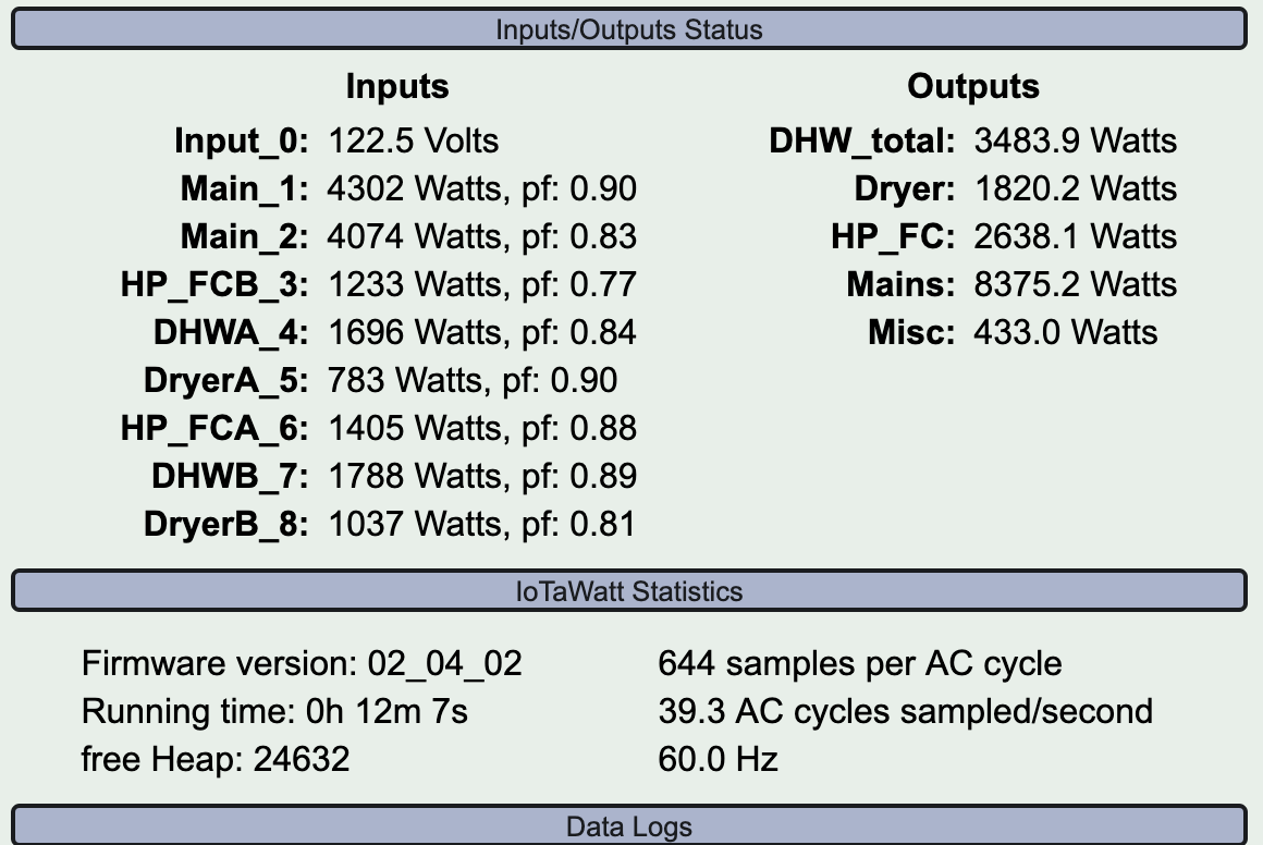
The negative value in Misc appears to be caused by that HP noise. You are subtracting 20 Watts that isn’t there.
To put these numbers into context, 20 Watts on a “doubled” circuit means it is sensing 83mA being used. That translates to a CT output of 83uA (that’s micro-Amps). 83uA produces 1.7mV in the IoTaWatt. The ADCs that sense the voltage have an accuracy of 1.6mV (two counts). The firmware throws away readings of 1 count as noise.
Try these things out and get back if the noise isn’t significantly reduced.
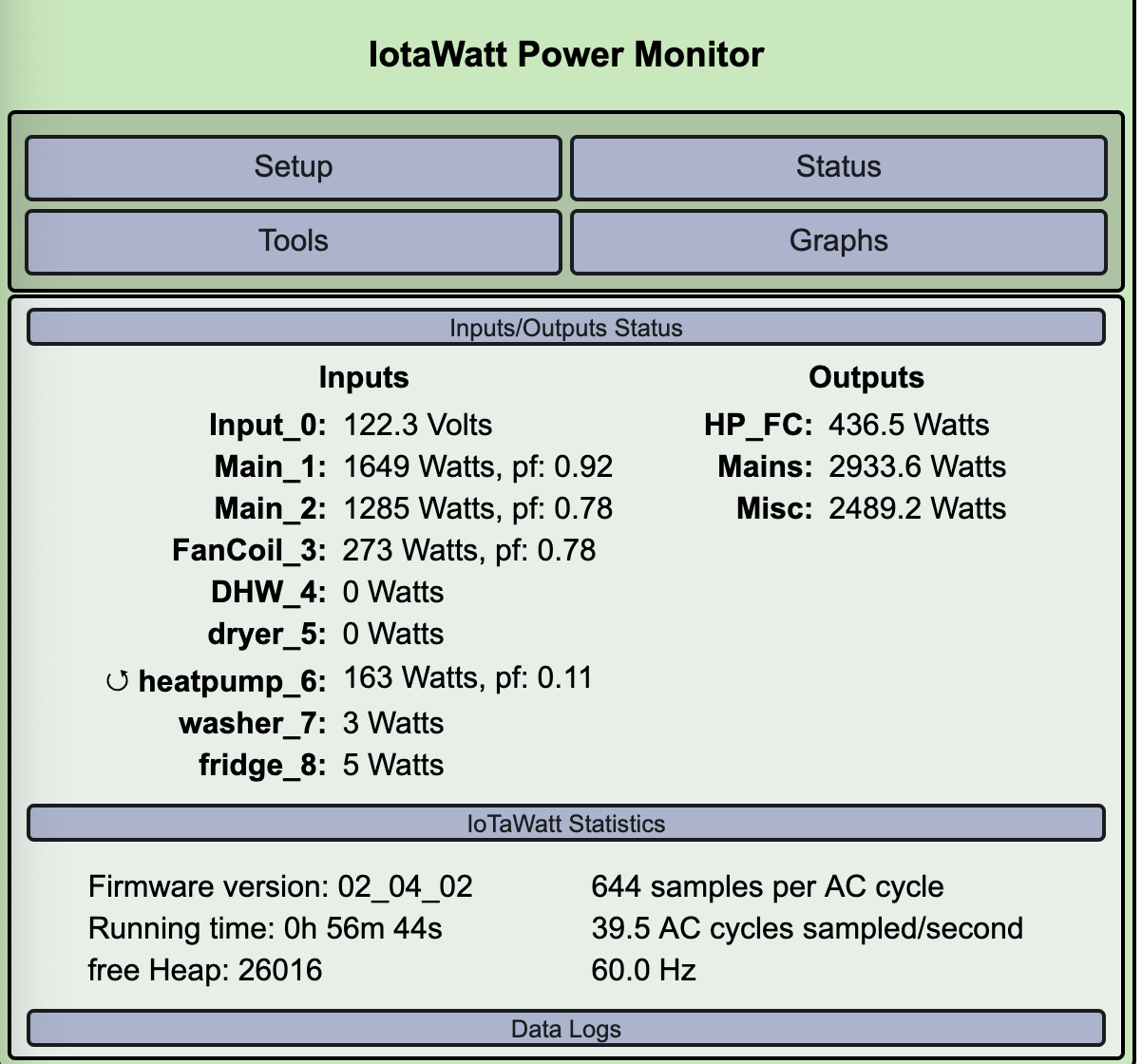
I ran both conductors through the CT and removed the “double check”. The results remain the same at 20 watts with the reverse symbol. Based on your reply it sounds like this behavior is to be expected, so I am not too concerned about it.
I do think my ‘Misc’ output calculation is suspiciously low, even when accounting for the 20 watts of noise from the heat pump circuit. I connected a CT to each unmonitored circuit one by one and recorded 105 total watts. The circuit for my Bosch induction cooktop accounted for 40 watts on standby alone:(
There are two problems here. The 20 Watts to the heatpump and the low misc value. For the low misc, you need to reconcile to the meter to see insure the mains are correct.
For the heatpump, can you try to see what changes it? Like removing the CT what does it read? With it installed what happens if you unplug it from the IoTaWatt? What happens if you swap it with the CT on the air-handler?
Your CT leads run down the middle of the box close to the circuit breakers and the main bussbars. What happens if you move the CT lead to the periphery of the panel? The noise is coming from somewhere, try to isolate the cause.
Bingo. You don’t have a standard split-phase system, you have two legs of a three-phase service.
That explains it. Not to panic, IoTaWatt can deal with it, to you are probably going to need more CTs.
First thing is to identify which of your main CTs the VT is on. One easy way to do that is to plug a hair dryer into the same outlet and see which main records the power. Note how much it increases for the hair dryer.
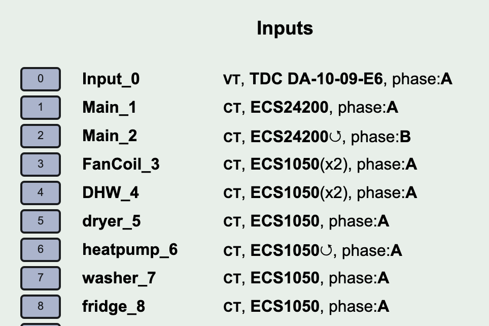
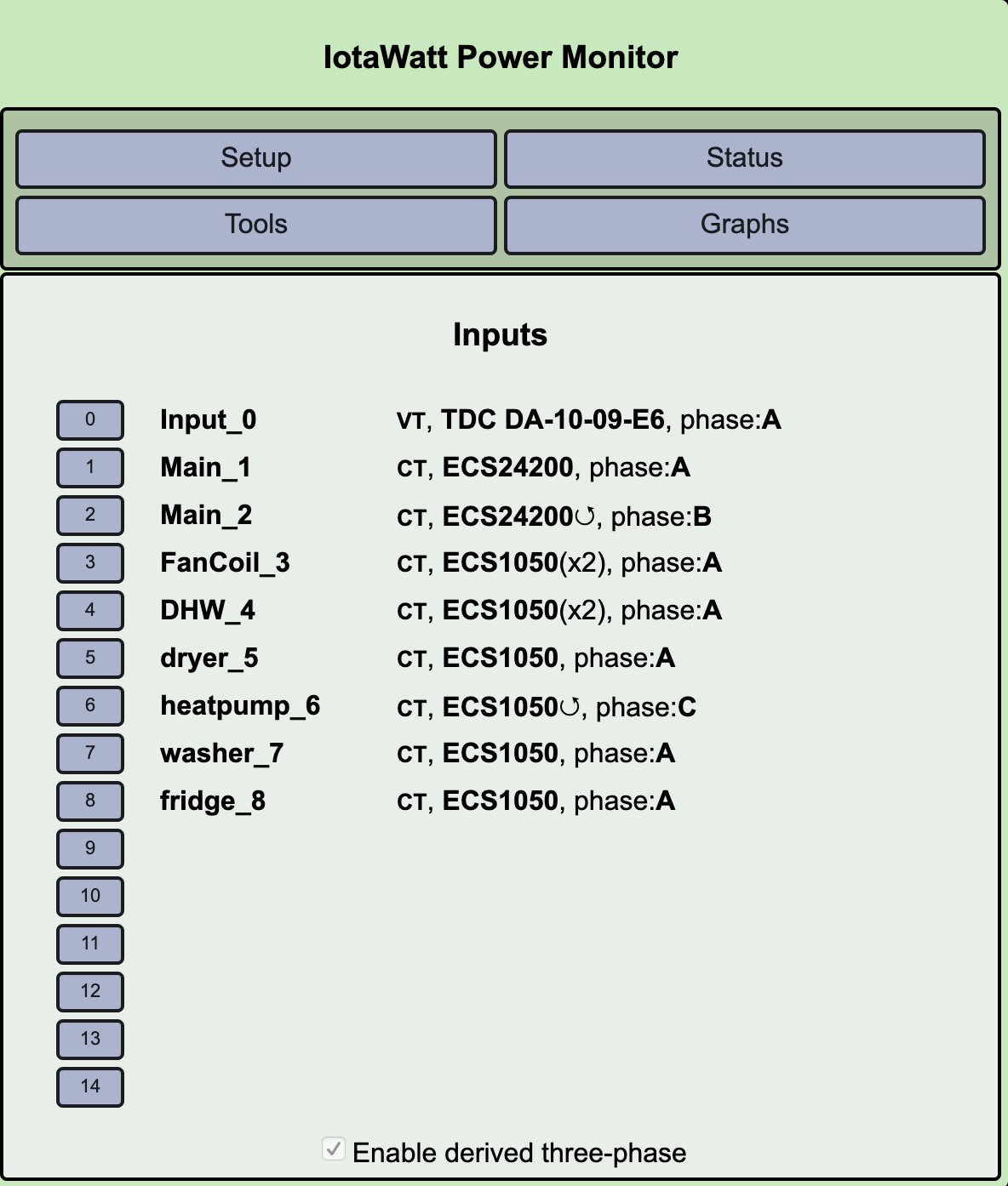
Once you do that, check the box at the bottom of the input configuration menu that says enable derived three-phase
All of your inputs will then have a the new attribute “phase” which will be set to A. Click on the main CT that in NOT the one identified in the previous step and change the phase to B.
Locate a plug that is on that CT and run the hair dryer. If the main power increases the same amount as you previously noted, this phase is correct. If it increases only half as much, change the phase on that CT to C and try the hair dryer again, that should show full value.
When you have done this, get back to me and tell me which CT is phase A (left or right) and what phase you identified for the other. Also, tell me how many 50A CTs you have. It will require 2 for each 208V appliance.
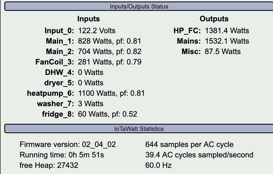
Good. Notice that your total main power has now increased so you have a higher Misc. It’s still not right because what you are subtracting isn’t all correct, but getting better.
You will need two for each 208 appliance.
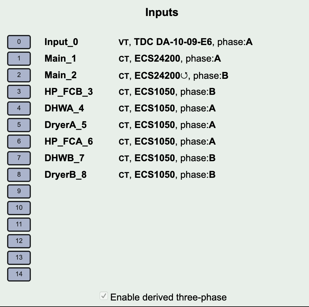
Your mains are black and red. So black is phase A and red is phase B. Your 208V appliances have black and red wires. When you install the two CTs, observe that for phase assignment. Adding the two inputs together will give you the total for a 208V appliance.
I notice that you have an output for HP_FC. You may want to just pass both black from the two through one of the CTs and both reds through the other. Change the red CT to phase B and add the two inputs for that HP_FC output. That would save two CTs and two inputs.
For the Hot Water and Dryer you can add two more CTs, or I can give you a constant that you can mutiply the single CT value by to get the power. For that matter, you can probably do that for the HP and FC as an alternative.
The washer and fridge appear to be on phase A.
So give me awhile to calculate the constant for the 208 devices.
Don’t tell anybody, but I make this stuff up as I go along. Have never approached this problem before, always full three-phase, but looking at the plot, I’d like to try something.
Can you set the phase for your heatpump to C and tell me what the it reads?
I’m just shooting from the hip here. The gold standard would be to use two CTs assigned to the black/red respective phases, but I think there is a simpler way. Let me think about it over coffee tomorrow AM and I’ll get back to you.
Your mains should be correct now, and I think worst case is 6 more CTs.
I look forward to hearing back from you once you have had a chance to think on this. I went ahead and used all my 50A CTs to connect to Black(A)/Red(B)on the 208v appliances and assigned the phases accordingly. Now my Misc power seems to look more like what I would expect. Thanks!