My panel has 2nred and 2 black wires coming in. How would I need to set up clamps to monitor this?
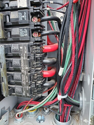
These Siemens panels are a problem to measure mains. There just is not enough room to install CTs in the main box and even if you could, would require 4 CTs. The only solution I’m aware of is to have an electrician with the utility’s permission, open the panel below the meter and install CTs on the incomming cables before the meter.
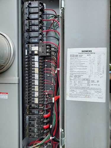
The other approach I would take is to just get a CT around all the loads and just sum them up. You’ll get the same information (total house load) plus you will get individual loads as well. The panel looks quite clean and with some clever combining you won’t run out of ports on the IoTaWatt.
You can use both the trick of running multiple wires through the same CTs or taking multiple CTs and combining them with “splitters”
See CT Basics — IoTaWatt 02_03_20 documentation for the details on combining circuits on the CTs.
Thank you both for the responses and ideas.
I just received my order today, I had ordered 2 of the white 200a CTs. I wonder if I would have been able to squeeze the black clamp on your into those wires. I might need to order some to try out
To @arnolddeleon suggestion, looking closely at your panel, it is very organized and the two phases appear to be strictly color coded (except for the 50A GFCI). So you can combine the reds and blacks directly. They all seem to head down and so can be easily bundled to combine. The wildcard is the 240V circuits and whether they are three-wire and/or can be combined.
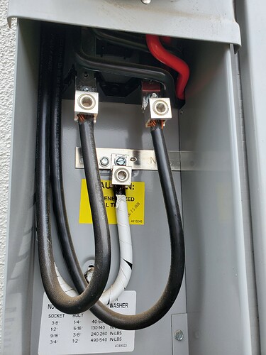
I have a little update. After searching this site for “siemens” i saw several other people with the same panel and then it clicked with your comment about the panel below the meter, so I popped it open and ta-da, wires! (NOTE: The panel was already unlocked)
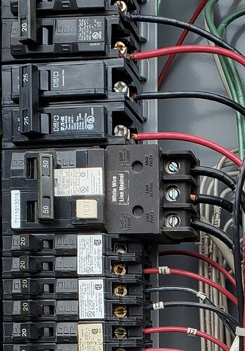
The 50A GFCI is for a hot tub. If I wanted to monitor that, would I go around all 3 black wires? It’s usually off 95% of the year so I may skip it to be able to monitor something else.
The 3 double size breakers near the top are for the mini split ac system and the 100amp near the bottom is for a sub panel. I was thinking of getting a second iowatt to monitor it from the other end. Also, my solar system feeds into the sub panel.
Don’t know exactly but I doubt it. A better pic where I can read the labels might help. It’s no doubt 240V but I don’t know what the third wire is.
The middle wire is a neutral, don’t know why they used a black wire.
You likely need only one CT around one of the outside black wires. If you want to be completely sure then you need two CTs but you can combine them into one input.
Whoever wired the panel did a great job with the red and black, I suspect this was added later. But there should be a piece of white tape around it somewhere in the box, and definitely at the other end.
In any event, yeah, it’s just a 240V three wire circuit. You will need to either use two 50A into two inputs, two 100A combined into one input with a splitter, or somehow run both hot through a 100A in opposite directions. See the docs.
Thank you all again. I have been doing some reading, the documentation is fantastic!
The middle/neutral wire does actually have white taped wrapped around in several spots throughout the panel.
I think I’m ready to move forward with this setup and then get a second order going for my subpanel.


