I believe i have a 3 phase 3 wire sub-panel that is fed from a 3phase 4 wire main panel. I’m trying to measure the total power of the sub-panel and a single 3-phase 3-wire load on the main panel. I’m getting confused with the VT and CT setup for the sub-panel and calculating total power of the sub-panel and an additional 3-wire load from the main panel.
Background
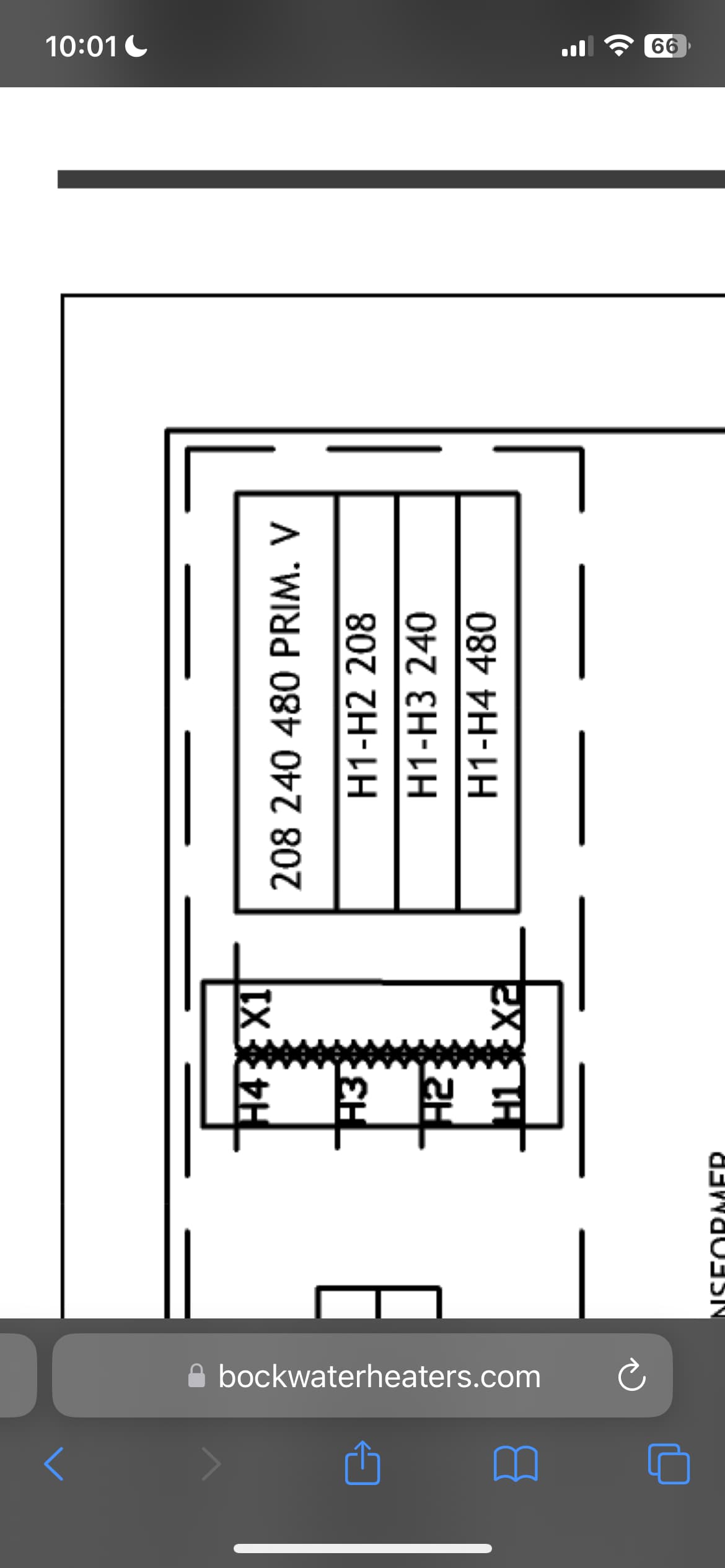
The building has a new installation of central heat pump water heaters. 12 outdoor heat pump units (Sanco model GS5-45HPC-0), significant storage, and an electric resistance ‘swing tank’ (Bock model CE119-1B with 3x 4,500 W elements) to handle the recirculation load during periods of low hot water use.
Our goal is to help guide this new installation to operate efficiently, and effectively tell the story of how we got it there so that other new installations can build upon the keys to success that we develop. We are using ‘total system efficiency’ to evaluate the system and the changes implemented. This total system efficiency is being defined as the ‘ideal heating requirement of the hot water’ divided by the electrical energy input to the system.
- The ideal heating requirement of the hot water is being monitored with flowmeters and temperature sensors. the total volume of hot water used by the building is logged, along with the entering cold water temperature and outgoing domestic hot water temperature.
- Electrical energy input to the heat pumps and swing tank is being monitored with an iotawatt
Electrical Setup & Monitoring
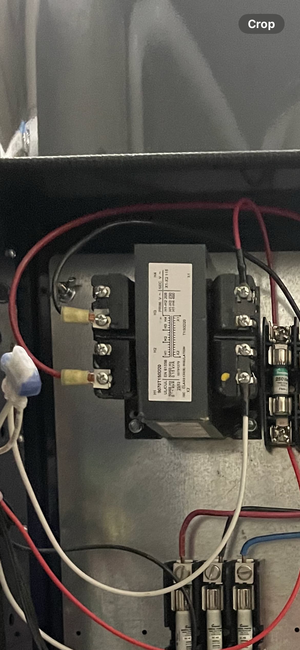
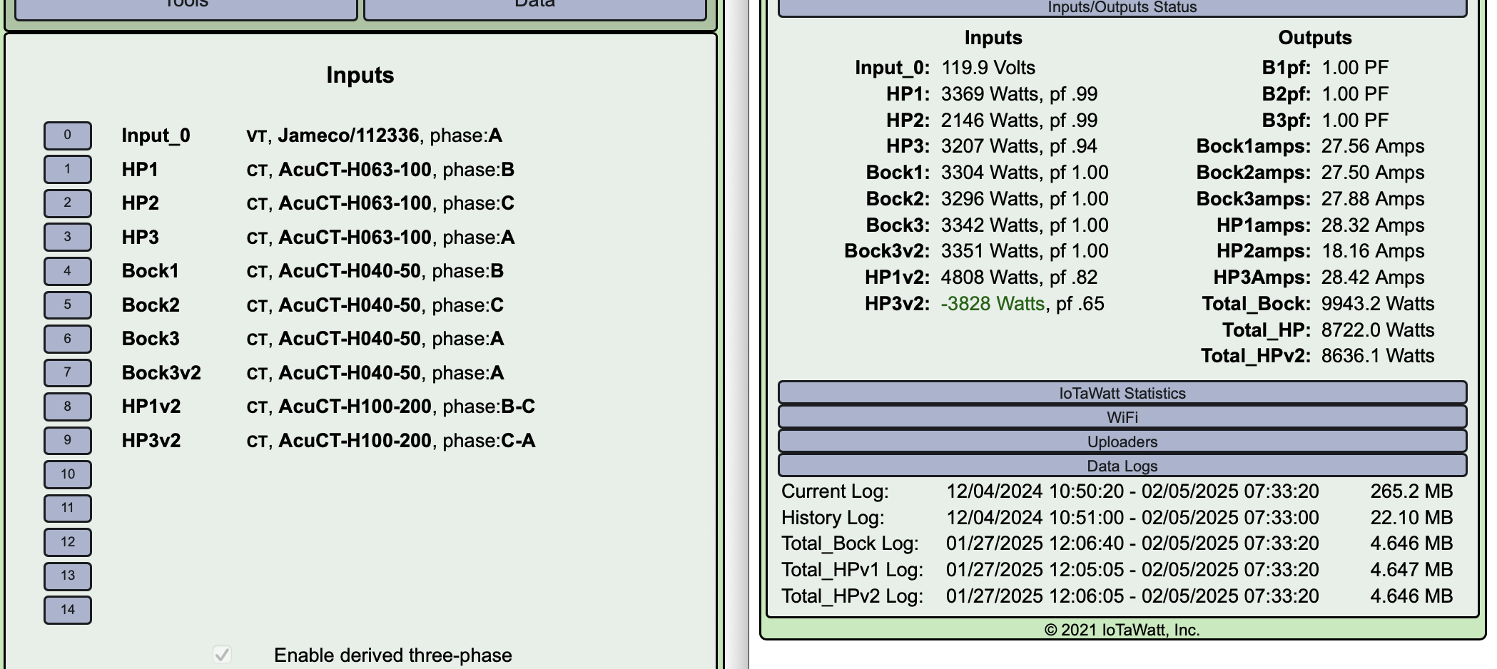
Using an iotawatt (i dont have a picture of model number at the moment, but it has the 3-phase AC Ref ports on the bottom) one default reference voltage transformer, and 6 CTs.
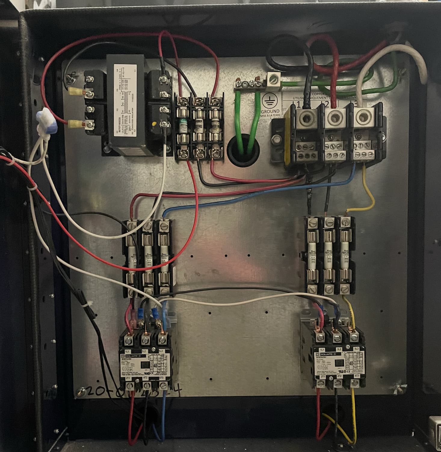
- 3 CTs are monitoring the incoming phases to the heatpump subpanel
- 3 CTs are monitoring the triple breaker that serves the swing tank. this is in an older existing panel next to the new subpanel (The outlet for the reference voltage transformer comes off this older main panel)
My current understanding of the electrical system:
The subpanel just has the three phase wires entering (black, red & white), so my understanding is that this is a delta configuration
- testing these shows ~208-211 volts between the phases.
- each heatpump has its own two pole breaker, with 15 amps marked on each pole.
The swing tank (in the old panel) has a three pole breaker (50A)
- Testing these three wires confirms to me that the black, red and white wires match the black red and white wires entering the heatpump subpanel
The outlet used for the iotawatt reference voltage transformer shows me its powered off the white phase. this outlet is off the main panel.
- tested with voltmeter from the outlet to the three phases of both the old and the new panel. less than 1V difference from outlet to white phase, and ~208 to red and black phases
Iotawatt setup
On the original install day i was in a rush and it was my first time. i figured i’d get accurate amp readings and voltage even without setting up the three phase settings in the iotawatt at all, so thats how i’d left it and been thinking about it over the last month
This week i returned to test phases, determine my phase A, see if i could figure out B & C, and configure the iotawatt to match
Determined the VT outlet is on the white wire, so this will be phase A for this iotawatt.
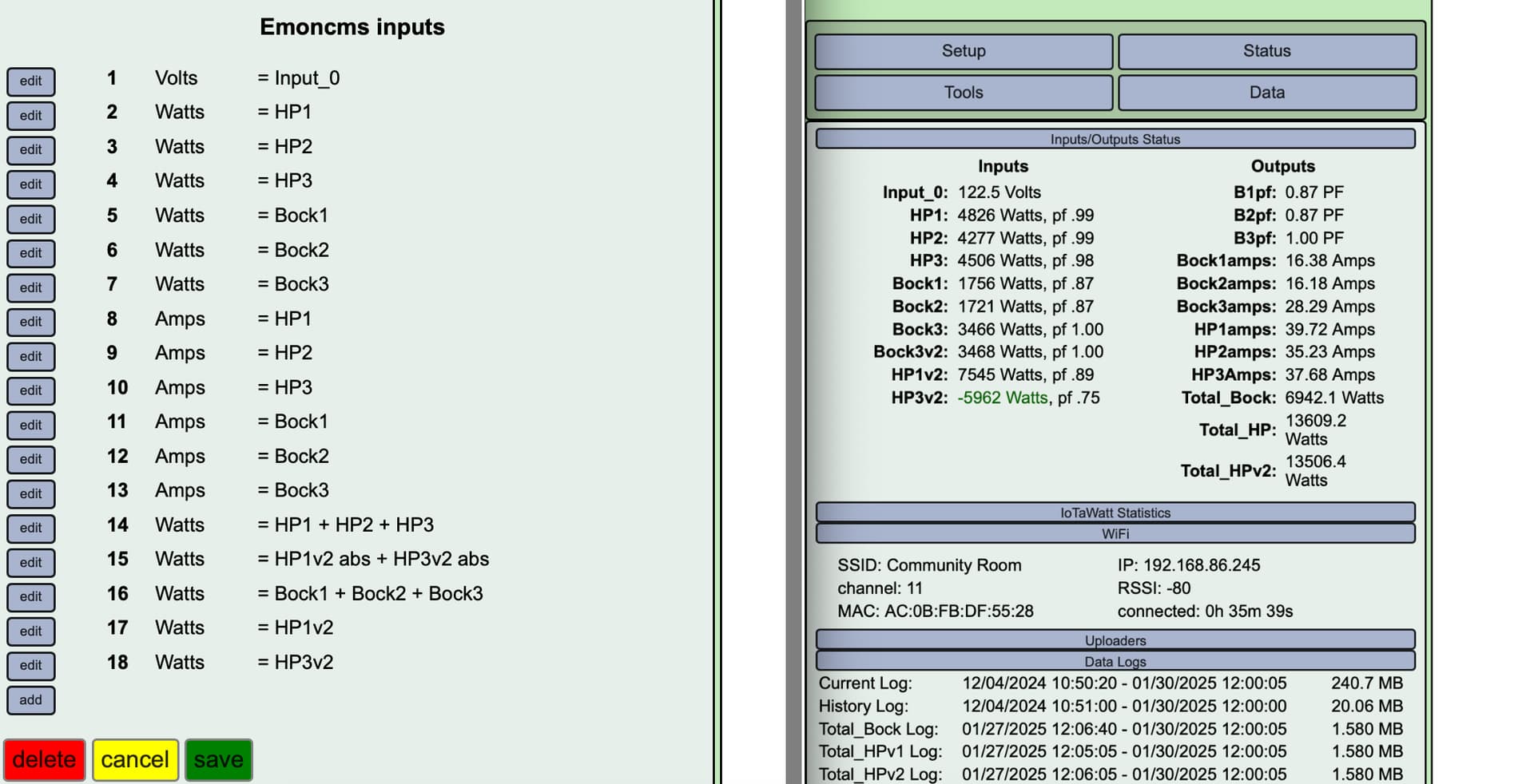
- When all phases were associated with the reference voltage (at 120v) (before checking off the ‘enable derived three phase’ box on the iotawatt), this was the only phase that had been reading a positive wattage, and had been showing a power factor very close to 1. the other phases had been showing negative wattages and power factors of .43 & .52
Adjusted the phases associated with the black and red wires based on which phase setting gave the highest power factor (understanding that this is not what the instructions say to do), settling on:
- Black Wire as phase C (+240°), which is wired into the left bus in the HP panel
- Red Wire as phase B (+120°), which is wired into the center bus in the HP panel
- White wire as Phase A as described previously. this is wired into the right bus in the HP panel
Confirmed with voltmeter that the black, red & white of the swing tank corresponded to the black, red & white of the HP panel (it did)
- adjusted the phase of those inputs
Adjusted the calibration factor for the voltage transformer from 11.43 to 19.72 to give me a reference voltage of 209.2v compared to my line-to-line measurements at the time of 209.6v, 208.8v, and 210.9v
- I don’t see instructions to do this anywhere, so this feels like it was likely a wrong move
Troubleshooting with forums
- I end up at this post: energy-meter-vs-iotawatt-three-phase-three-wire-delta which leaves me questioning if my line to neutral VT makes sense if it should be calibrated to 120 or 208v
- and this article that overeasy has linked to: yokogawa-how-to-measure-electrical-power
Questions
1: Phase mix-up (please call me out if it sounds like i’m wrong, understanding that i chose phase B & C based on power factor readings from the iotawatt)
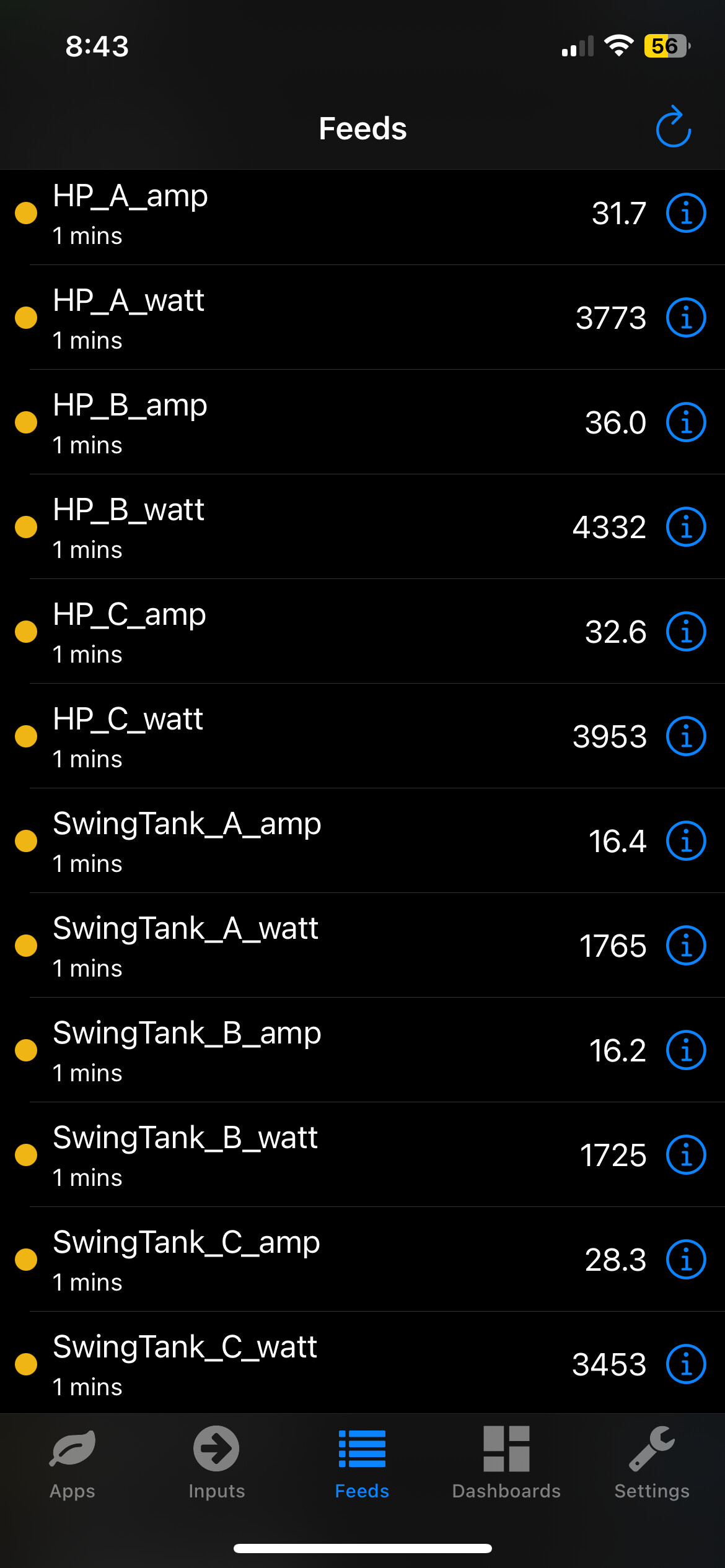
- when i attributed the phases to the electric resistance swing tank, the resultant wattages didnt make sense to me, so this raises questions for me about my whole process: wire 1 has 0.24 amps set as phase B, shows 16 watts; wire 2 has 0.13 amps, set as phase C, shows -2 watts; wire 3 has 0.05 amps, set as phase A, shows 0 watts
2: Reference voltage, i calibrated it to 209v thinking that this seemed appropriate , but not sure if i should’ve (didn’t feel like this was addressed in instructions i saw)
- my current thinking is that i should change this back to its original calibration to 120v line to neutral
3: Iotawatt amp readings are not matching the central Heatpump controller (iotawatt is about double), is there potential for mixup in the amp readings?
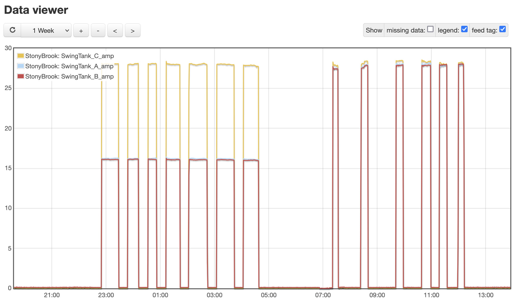
- I think that the amp readings of the CTs are the raw data and not impacted by any of the voltage or phase adjustments that i’ve made. reviewing the logs of amp readings seems to support this as typical values have remained unchanged before/after these adjustments
- my newest understanding here is that i should be averaging the amp reading of the three (or two?) wires, not adding them
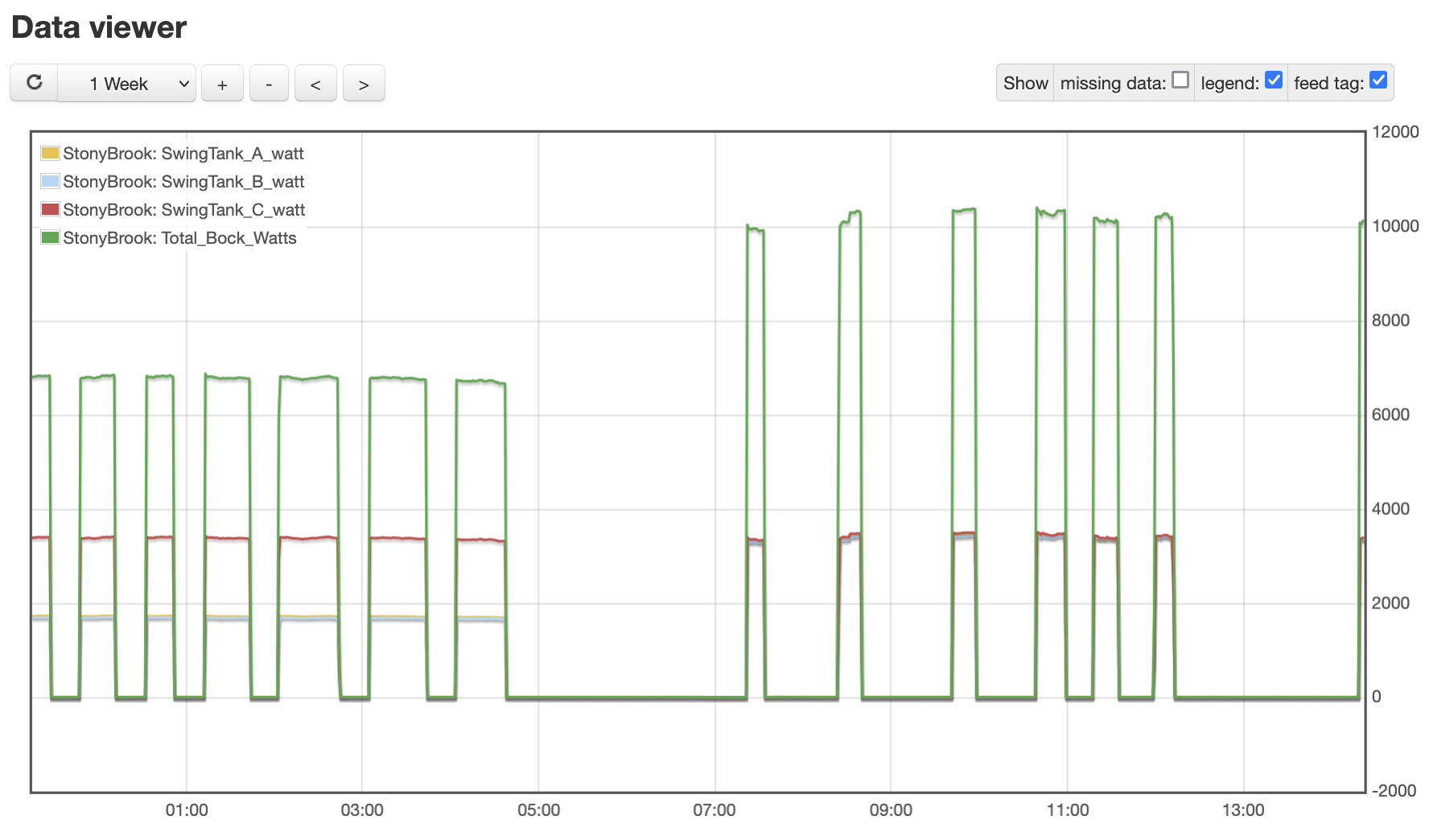
4: I’d felt confused on wattage for each phase, and combined wattage. and my current understanding is that i just shouldnt worry about phase wattage, and should just do total wattage with the 2 wattmeter technique.
- phase wattage = (line to neutral voltage) * (amps of this phase) * (powerfactor for this phase)
- Total wattage = sqrt(3) * (line to line voltage) * (average of phase A, B & C currents) * power factor (i’ll say the average)
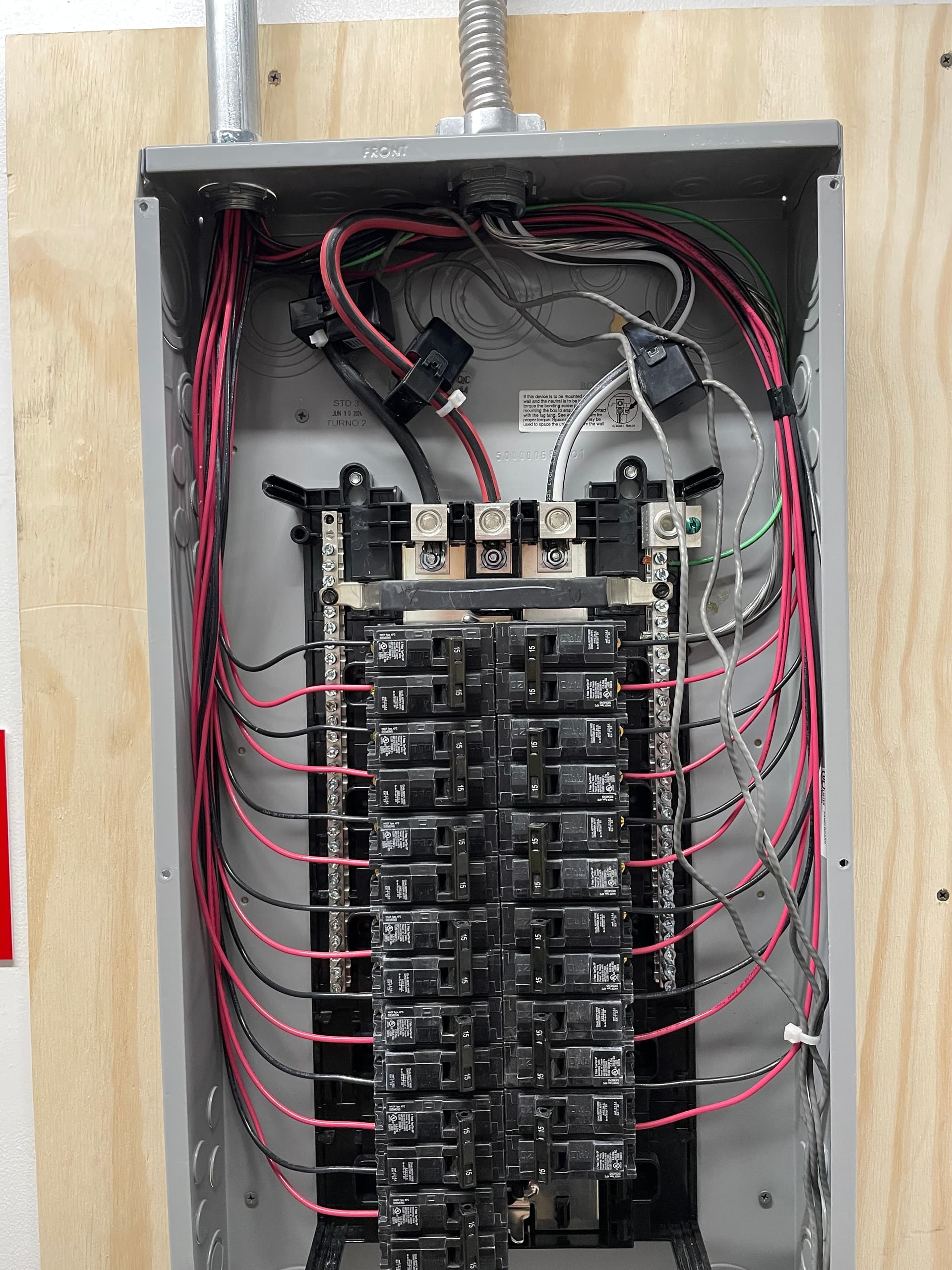
Sub-panel:
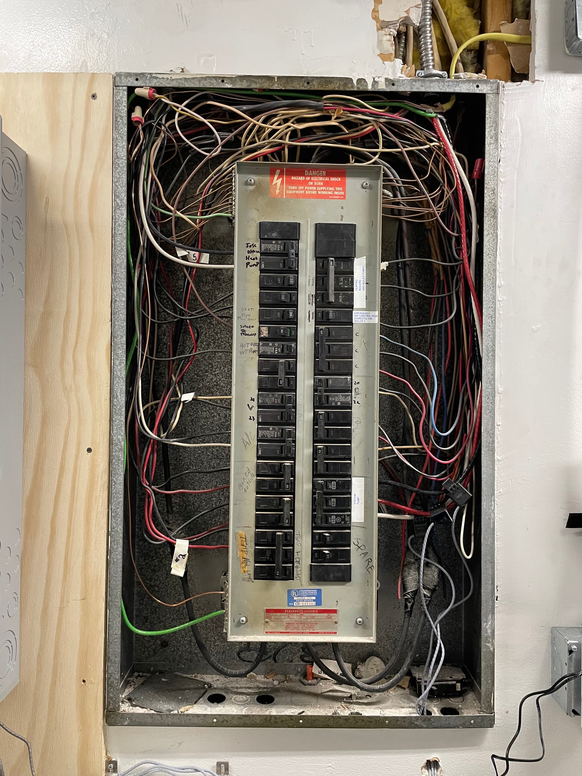
Older Panel:
Iotawatt showing phases, amps, and wattages. voltage calibated up to ~209
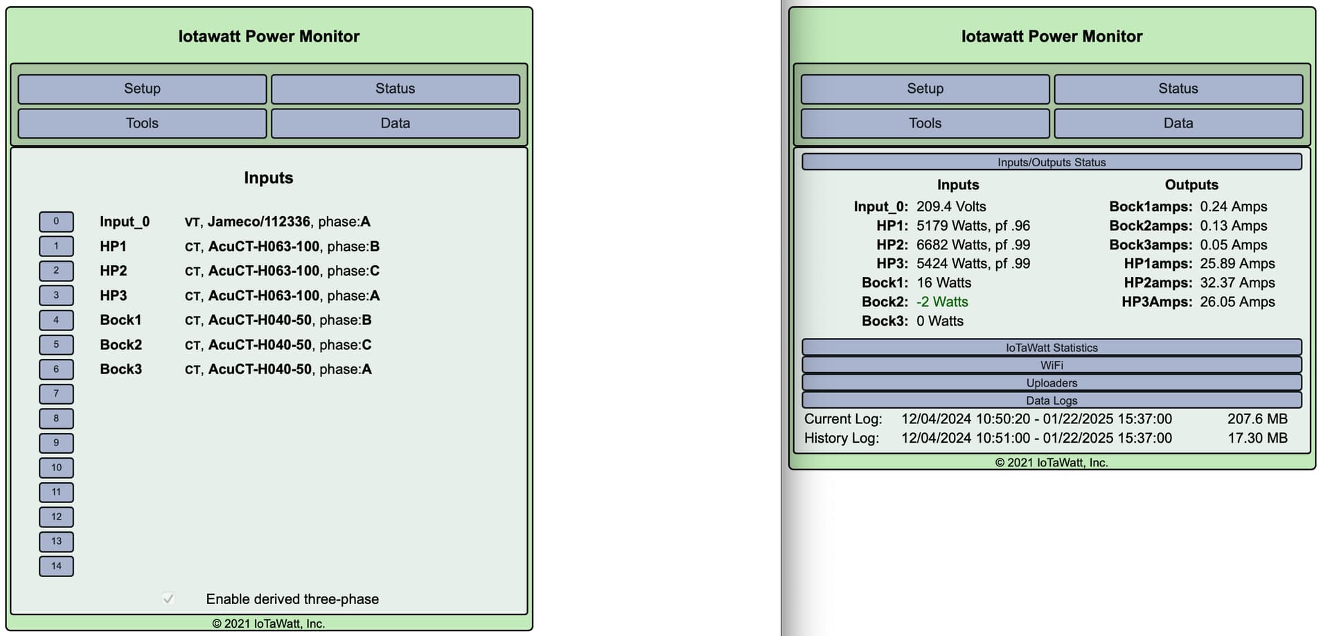
Thank you so much for your help!