3 phase input with a single CT

Hi,

I have a 3 phase system - it is setup with with a single VT, so far so good.

one of the load I’d like to monitor is 3 phase as well (used for EV charging). Given that i don’t have enough input port available, can I use a single CT (ECS16100) and clamp it over the 3 wire?

Thanks!

That will not work. You can probably get a decent approximation by clamping on one wire and multiplying by three.

If the charger is three wire (no neutral) you can monitor with two CTs. It’s a little more complicated, but I can work you through it. Post back if it is three-wire and you have two CTs available (50A or 100A are fine).

Hey @overeasy Thanks!

yes the load is unevenly distributed across the three wire (there are two single phase plugs - used with standard home chargers, and a three phase charger).

Please let me know the config I should be using with two CT - Thanks again

Don’t know what you mean by this. Can you provide a line-diagram to explain this?

Sure

That circuit is connected to a small cabinet containing two single phase sockets and a three-phase socket.

L1 -> Tesla UMC (mobile charger), single phase rated @2.7kw (12A @220v)
L2 -> VW mobile charger, single phase rate @2.2Kw (10A @220v)

L1+L2+L3 -> Tesla UMC (mobile charger), 3-phase rated 11Kw (16A per phase)

The Tesla UMC is either used single phase (L1) or 3 phase (by swapping an adapter)

Hope it is clear now - Thanks!

So are you trying to measure just the three-phase charger, or all three chargers by monitoring the total load of the small cabinet? With two single phase chargers, there must be a neutral wire going to the cabinet. Do you have a picture of the plug for the three-phase charger?

I would like to monitor the consumption of the whole circuit (I don’t care about the single plugs) using less CT possible.

Yes the circuit have the neutral as well - the plugs are derived in this way:

  • single phase socket1 L1+N
  • single phase socket2 L2+N
  • 3 phase socjet L1+L2+L3+N

OK, the three-phase plug is four-wire (has a neutral) so not possible to do with two CTs.

If I understand you correctly, you would like to monitor the aggregate usage of the three EV chargers. That is only possible using three CTs. With the single phase units, even the approximation by multiplying one phase by three will not be accurate.

If you don’t have three inputs available, maybe the solution lies elsewhere in combining other loads to free up extra inputs.

thanks @overeasy very clear now! I will repurpose later 3 inputs that I’m trying to use today to monitor the 3 phase coming to my first breaker.

I still have a bunch of other questions regarding 3 phase systems - and I was not able to find hints in other forum posts.

Do you mind if I ask here or should I open a new thread for each topic?

Again thanks for your help

Fire away. If they deserve a separate thread, I’ll move them.

thank you thank you thank you

better description of my system - it’s a EU 3 phase and as described earlier I have 4 wire (3 phases + neutral). I have also a Solaredge systems, equipped with their own CTs.

To have the maximum amount of inputs I’m using a single VT and derived 3 phase.

Question 1)

I would like to group two load into one. They are the lights of my house at ground floor and floor1. The problem is that (for trying to keep the phases balanced) those loads are on different phase.
Is there a way to monitor (aggregate amount is fine) the two loads with a single CT?

So far I tried using a single CT with the two wires of the loads and configured the input with main phase = B-C (+90°). B and C are the phases where those loads are connected to.
The measurements looks to be right but wanted to confirm if is really a way to accomplish such or should I really split the load under two CT?

No.

b-c would be the phase/voltage reference if the load were single-phase 400V - two-wire with phase B and C, no neutral. There are two common uses for the phase-to-phase references:

  • As voltage reference when using two CTs to measure a three-wire three-phase load.
  • As voltage reference when connecting a single-phase load between phases as in a US 120V/208V panel.

You need two CTs for the two loads.

Maybe if you post a picture of your breakers and wiring, I might have some additional insight into your problem.

ok will take pictures of the cabinet - there are a bunch of panel to be removed

can i combine the two load using two CT but with a single input?

Not if they are on different phases. Each input is associated with one voltage/phase reference.

If they are the same phase, you can do it as per this from the docs:

Two individual CTs can also be combined with a common headphone splitter and fed into a single IotaWatt input. When combining this way, both CTs must be the same model with an individual capacity sufficient to measure the combined capacity of the two circuit breakers.

1 Like

Ok seems like I will have to move lights under the same phase and plugs under the other

This is my panel:

From below I have the phase coming from the grid provider - here is where the circuit is derived to feed also in my solar system (based on solaredge will have questions regarding this later)

From below I’m also deriving to a dedicated panel for EV charging (described earlier) and one of the phase is also supplying power to a different apartment (attico)

then I go up into the main breaker of my building, then the three phases are divided into 3 different differential protection

You can see also the actual configuration of the CT

and here is also how those are configured in iotawatt

and here is the readings now

You already answered Question 1. Thanks a lot I will have then to move the load Prese PT and Prese P1 under the same phase, and Luci PT and Luci P1 under the same. In this way I will be able to share two wires in the same CT.

The only thing is somehow curious is that the actual reading of CT4 and CT5 seems to be quite accurate. Particularly some testing done with CT5 (lights are very very consistent).

Second Question:

Solaredge report, correctly zero (or very close to) feeding/load from the grid (which seems to be very reasonable since i have 10kwp of solar and 20kwh of batteries) iotawatt is seeing different numbers.

While the load on the 3 phase can be different from zero, I’m trying in fact to investigate how the solaredge is feeding and loading the phases, I don’t understand why the aggregate is not zero in iotawatt.

I noticed very rarely phase L3 (A) being more than 0 which seems to be strange.

Is the input correct? could it be that CT3 has something wrong?

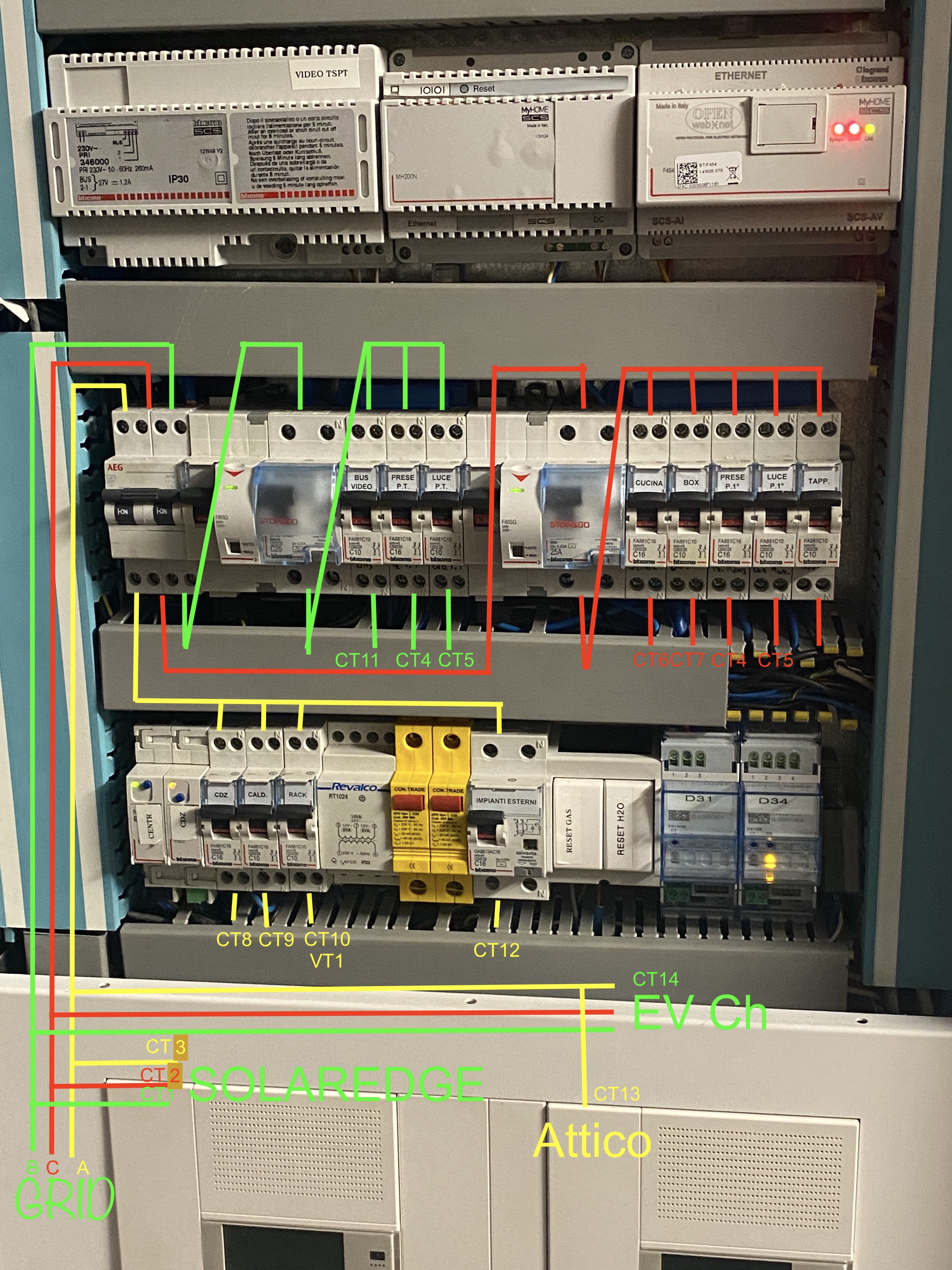
I can’t see the actual wires, so everything is based on the color-coded circuits that you have added.

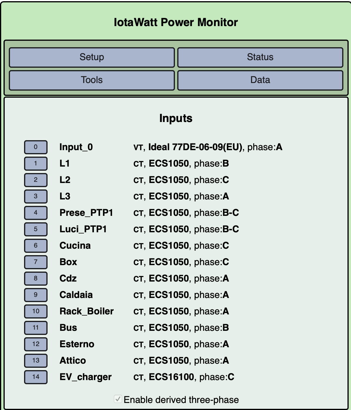
I’d like to understand exactly what you want to do with the SolarEdge. Given that you have 14 inputs, I’d suggest the following:

3 CTs on the Grid lines upstream of the Solar-Edge. This will measure what you use from the grid and what you export to the grid.

3 CTs on the Solar-edge. This will measure what your PV/battery system provides, and anything that it might happen to consume (don’t know the battery strategy).

3 CTs on the EV charger.

1 CT on the Attico line.

At this point you will know what you import/export to the grid.
What your PV system is adding/using.
What the Attico apartment is using.
What the EV chargers are using
and importantly, by computation, what each of the mains above are using, and by extention what each of the downstream breaker groups are using.

So now you have used 10 inputs, you can select up to four additional circuits, or groups of circuits on the same phase, to measure individually.

With IoTaWatt’s calculator outputs, you can then determine what the sum of the unmeasured circuits on each. So where you are trying to measure three individual circuits on L2, you could measure one of them, and knowing the total of the three, create an output with the sum of the other two. Same for L1 and L3. The four additional CTs will effectively give you eight additional circuit groups.

If you want to rely on the SolarEdge monitoring, you can get by with:

3 mains CTs downstream from where the solaredge feeds the grid lines.
3 CTs on the EV
1 CT on the Attico,
That leaves 7 CTs for individual circuits, and as above, you will know the aggregate for each phase through the main breaker so you can get metrics for up to 10 circuits (or circuit combinations on the same phase).

Back to basics. The documentation for derived reference describes how to configure the mains. It’s very important that all of the CTs that you install be oriented the same way. There is a procedure for determining which circuit is phase A. This is very important. I don’t believe you have it right. Once you get that right, follow the procedure for determining the other two.

color is accurate

the solaredge system has already 3 CT on its own - I really need to understand what it’s doing with the grid, so no need to monitor the PV phases - so I will proceed with the last portion of your suggestions - thanks!

I setup phase A following the documentation - Phase A is surely correct as it’s the same where the VT is connected. B-C I’m quite sure as it’s the config delivering consistent results.

Can I ask you why you think I got it wrong?

For the grouped load configured with B-C (e.g.) I’m not sure I understood the difference - you mentioned a single phase 400v - in my case, while it’s not intentional, the way I grouped it’s going to be that way:
Those are two singled load @220v - but when grouped the voltage difference between two phase it’s 400v. I keep asking because the power reading looks really really correct?

I’ll try to replace CT3 and see if a spare one is reading different values.