I just thought I’d share my install incase it can be of help in the future to others.
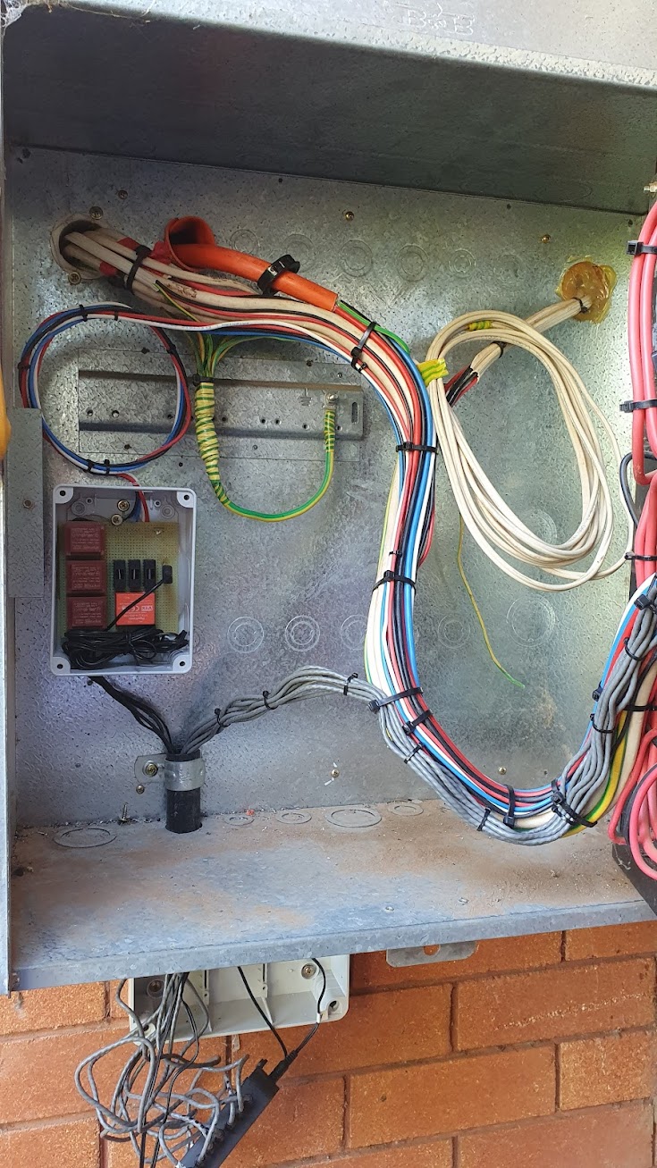
I’m an electrician in central NSW, Australia and my house has a 3 phase supply and will soon be installing 12kW of solar. I’ve installed my monitor with 3 VT’s and currently have 9 CT’s connected (3 for incoming mains, 1x House switchboard, 1x Hot water, 1x Indoor Spa, 3x 3 phase shed switchboard)
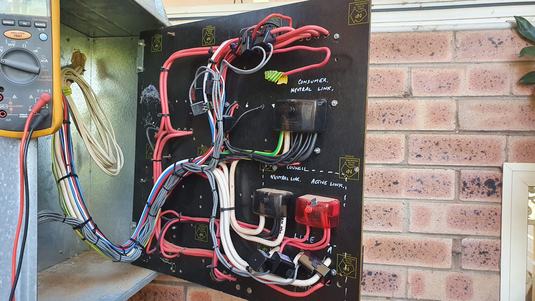
I made my own circuit board with the 3 VT’s 5VDC supply and USB outlet for the IotaWatt power supply and fuses to protect the line side of the VT’s. When I first powered up the VT’s were putting out close to 16V as they are only 2.3VA so i have installed 33Ω resistors across the outputs to pull down the voltage - now around 9.6V output at 250V input.
Once I powered up I had quite a bit of trouble with the voltage direction being inaccurate - ie. say when my spa is just running the circulation pump ~100w the power read out was in the correct direction but once the filter pump kicked in the power read out was in the negative watts. To circumvent this I created a star point with earth reference on the secondary side of the VT’s which has corrected the issue.
I have also set up with Home Assistant to monitor the daily usage and costs (not without a lot of stress as I’m only new to the platform)
This is a nice bit of work, and very neat and tidy. But there are some issues that you might want to revisit.
This is very troubling. Direct reference installations typically use three independent wall transformers and have no problems. Without seeing your exact wiring, and checking the phase relationships, I can’t determine what may have caused your problem, but I suspect it has to do with your VTs and possibly your DC supply.
IoTaWatt is designed to have floating voltage (and current ) inputs. Connecting them together, and connecting them to ground, can easily damage the IoTaWatt or cause erroneous readings. I would recommend that you revert to each VT wired independently to its IoTaWatt input plug, with a 4.7K series resistor and no shunt.
I calculate that the 33 Ohm shunt is drawing about 270mA and 2.5 Watts. That’s a lot of power just to reduce the voltage! The IoTaWatt VT inputs use a 12K + 1K voltage divider, so 13K total. If you add a standard 4.7K resistor in series, you will reduce the voltage seen by the IoTaWatt to about 12V and go from 2.5Watts to 15mW, any standard 1/4 Watt resister will work fine.
Do not tie any of them together, and don’t ground them. If you have grounded the negative of the DC supply, uncouple that as well. Let it all float. If that still causes negative readings, get back to me.
Would be cool to have a pre-made 3-phase VT that also provides the USB power!
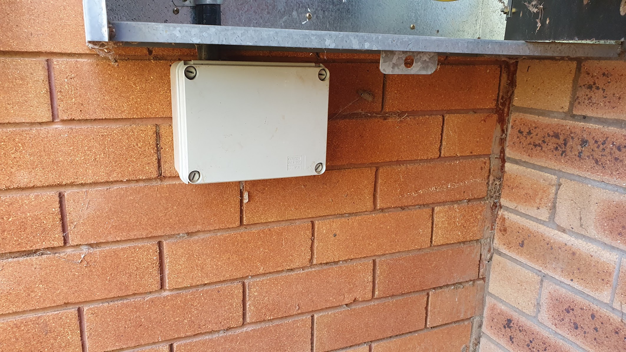
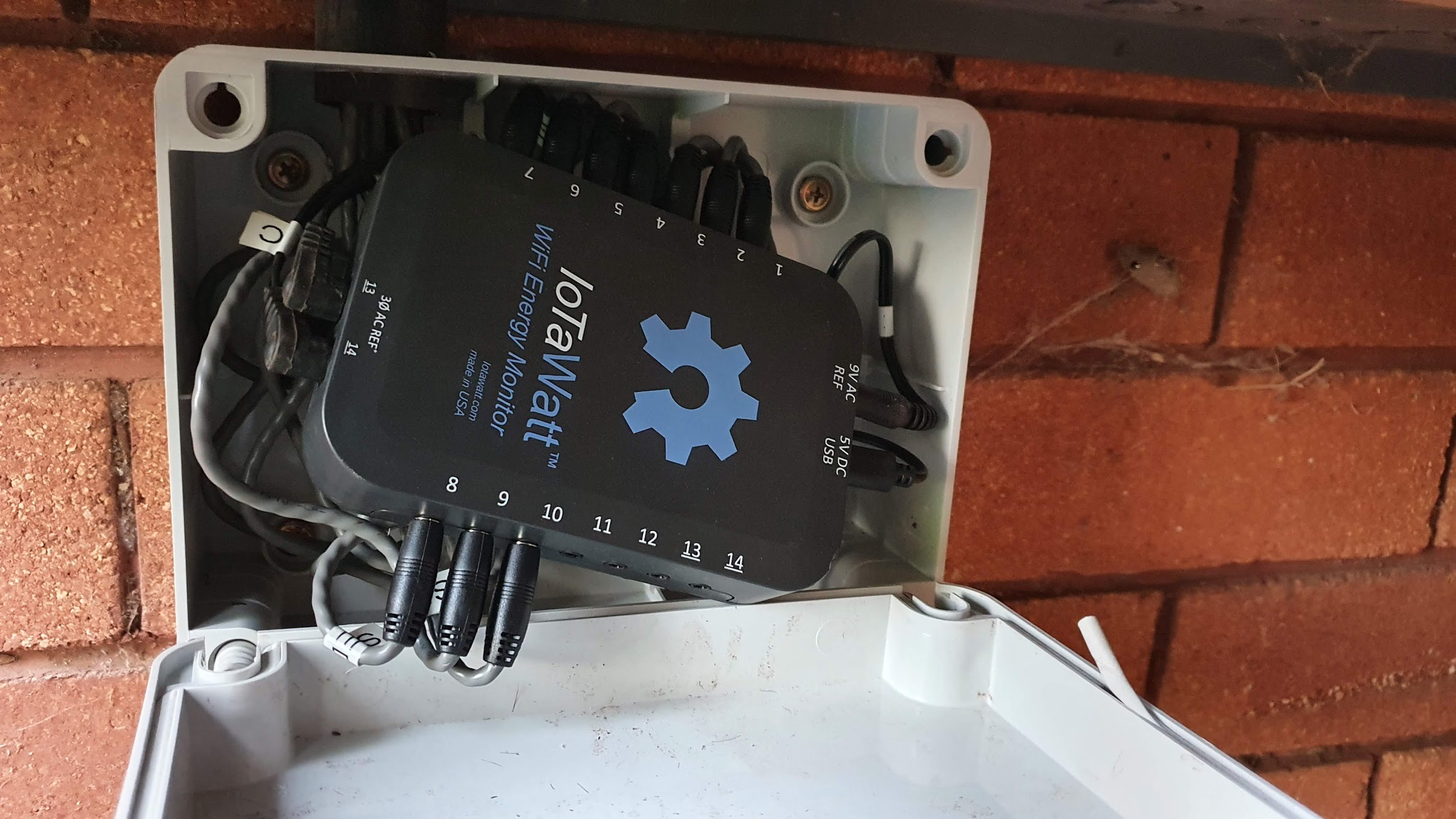
What case is that? It looks a bit tight. I’m on a hunt for one in Australia that I can mount but the one I got from Jaycar doesn’t fit with the annoyingly long headphone jack plugs on all sides.
Is it possible to change the ESP8266 to a model with an external antenna connection? That would solve my mounting issues.