400A panel (320A) service with solar/batteries

New to IoTaWatt but experienced with other energy monitoring methods. I have a moderately complex installation so I am asking humbly for purchase suggestions. As the title indicates, I have 320A service coming into a single panel (Siemens E4242MB1400CFU) rated for 400A. Solar with power walls are also used with inputs into the large panel. There is a 200A sub panel within 18 inches of the main in which I would like to monitor some things. I have 4 power walls but they are physically separated from the main panel by >20 feet in a crawlspace. Electrical schematic attached.

Goals:

  1. Whole home consumption monitoring with accurate solar production/net metering.
  2. Individual circuit monitoring for some but not all (ie GSHP furnace x 2, EV chargers, Hot water heaters, appliances, etc) totaling likely less or equal to 14 to start.
  3. Would like to be able to monitor powerwall charge/discharge status but likely more complicated and not absolutely necessary (am already monitoring with other methods but without the granularity I would like).

Thanks for suggestions and sorry if this is inappropriate to post - will delete if so.
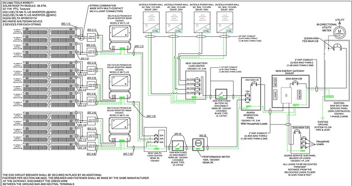
By the line diagram, it appears that the PV generation can be measured as if it were a single 20Kw system. You could break it down to see the individual output of each inverter, but that would require additional inputs.

Same goes for the Powerwall. I believe they can be treated as a single powerwall by monitoring the Battery Load Center. You could break it down to see individual batteries but would probably require another IoTaWatt assuming that panel is also >20 feet away.

Not too clear on how the Energy Gateway works. Is that the Powerwall Gateway? If so, it would seem that the “backed up loads” should be in the Generation Panel and other non-critical loads would be in the Service Sub-Panel.

The old main panel is a 400A panel. The reason it’s designated as 320 continuous Amps is that any protected circuit should be protected to 125% of the expected load, so 400A protection for 320A. By the same token, a Panel protected to 200A should see no more than 160A continuous.

From the line drawing, there is only one load on the old 400A main panel and it feeds the Energy Gateway with a 200A breaker. Unless there is something more going on, it would appear you effectively have a 200A service. Perhaps the thinking is that with the PV and batteries, you will not exceed 200A from the grid.

The end fed CBs mean the load is fed into the panel from the opposite end where the grid feeds in. In that way, the main buss will not exceed the mains rating even if the mains are providing 160A and the PV is providing 80 Amps.

So, without knowing exactly how the backup works, my first pass is

2 x 200A Main Panel Feed (will measure grid import/export)
2 x 100A PV Load Center (will measure PV generation)
2 x 100A Battery Load Center (will measure battery charge/discharge)
2 x 200A Generation Panel (will measure Household Loads)
2 x 200A Service Sub Panel (will measure Household Loads)

It may be necessary to monitor voltage in both the service panel and the Generation Panel depending on where the switch is made on grid outage. I would think that would be in the Energy Gateway, but it does not appear that there is any way to segregate the loads in the Generation Panel when running on battery.

That is quite a complicated setup. There is a lot going on. You need to do some math to figure out exactly (or close enough, at least) how many channels you need to get the granularity of data you need/want. Do you want data on your individual inverters (it looks like you have 7 of them)? If you do, that would probably take 14 channels (assuming each inverter is 240/120V capable). If you want the aggregate info only that could drop it to 4 (if you want solar seperate from PowerWall) or only 2 if you only want to know what is being used/provided inhouse.

There is information on how to figure out if you need 2 or only 1 CT for each circuit you want to monitor. You should probably take some pictures of the various panels to see how easy it will be to put CTs (and which ones will fit) in the various locations.

To get your basic needs you need:

  • (2) 400A CTs - for the main service panel
    With just that you can answer net metering. You will not be able to tell how much came from solar.
  • (2) 100A CTs - for the solar panel
    This will get you what the solar panels are providing, but not individual information about the panels/inverters. They might have that information already, so getting it independently might not be necessary/worthwhile.
  • (2) 100A CTs - for the PowerWall panel
    This should probably be 200A CTs based on the possibility of going above 100A (not sure that is very likely).

That leaves you with 8 inputs left on a single Iotawatt for measuring other circuits:

  • (2) for the GSHP furnaces (it is likely 240V only, so only needs one 50A or 100A depending on the size)
  • (2) for the aux heat on the furnaces, assuming you have aux heat
  • (1) for each EV charger (if you have a smart charger, perhaps you don’t need to monitor it in Iotawatt)
  • (1) for each water heater

You don’t have a lot of inputs left for anything else and don’t have detail on the multiple solar and PowerWalls, so it might be worth considering more than one Iotawatt. Going beyond 1 means that you probably want to use something to aggregate the data from the multiple sources. This increases the complexity some, but you are already well into complex.

Yes, you can create an output that nets the two feeds to come up with what the mains should be doing. Call me old-fashion, but I cut my teeth doing computer business systems and got used to double entry bookkeeping. When both sides of the ledger balance, you know it’s right…

You don’t need a ladder. I’m talking about putting the CTs where the feed enters the emerge gateway.

I doubt it.

Maybe so.

Same basic answer as before except the burden would need to be changed to 5 Ohms.

At the end of the day, the maximum voltage should equal 1 Volt. The CTs output 50mA at their rated capacity so:

0.050 Amps x 20 Ohms = 1 Volt
0.05 Amps x 2 x 10 Ohms = 1 Volt
0.05 Amps x 4 x 5 Ohms = 1 Volt

Be sure to change the burden in the setup.
Configure two combined as a single generic CT with 8000 turns and phase 0.25.
Configure four combined as a single generic CT with 16000 turns and phase 0.25.