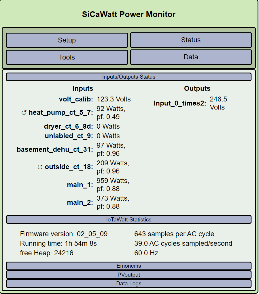
Hi - just bringing the IoTaWatt up. I do not understand it but the input CT’s are going in the same direction (away from the circuit) but some but not all show as reversed on the status. Is that possible? Should I just reverse?
Hi Bob - I had read that and the " Mains CT orientation" and " Load CT orientation". I did reverse the ones that had the symbol. I posted because it did not make sense to me that if all of the CT’s were in the same orientation, it’s hard for me to understand why some are reversed and some are not.
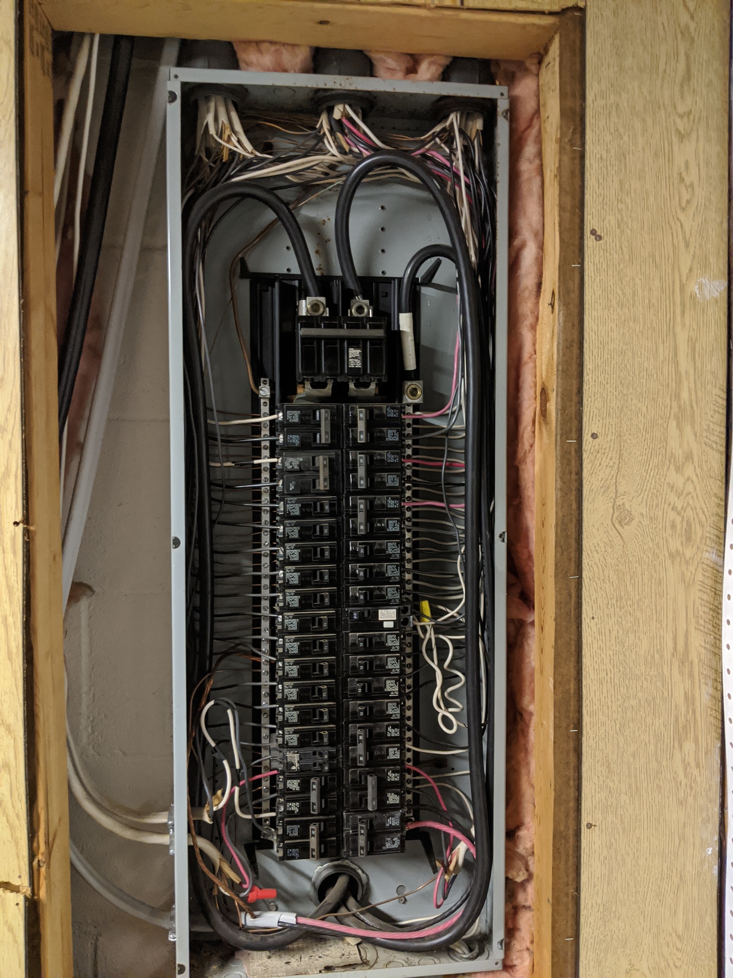
The rows of circuit breakers in your panel alternate between connecting to the left phase and the right phase of the split-phase supply. Your IoTaWatt is using a single voltage reference, connected to just one of the phases, to calculate power for all of the breakers. So all of the breakers connected to one of the phases will be positive, and all of the breakers connected to the other will be negative because they are using the voltage reference from the opposite phase, which is the exact opposite voltage.
To better understand this concept of the voltage of one phase the opposite of the other, consider that your panel supplies both 120V and 240V. Notice that wherever you have a 240V breaker, it’s actually two breakers in adjacent rows of the panel, so the two breakers are on opposite phases. When one phase alternates to +120V, the other alternates to -120V. The difference between the two is 240V. You can measure the total power in that circuit by passing the two 120V conductors through the same CT, but you have to reverse one of them through the CT because that reversed conductor is connected to the other phase, where the voltage is reversed.
While the 120V circuits will automatically correct if reversed, you need to understand this concept to properly measure 240V three-wire circuits. That is explained in the referenced docs.
I know this is an old post, but I had the exact same question which brought me to this post. It may be worth making it a sticky or mentioning something about this in a documents/installation page. This is just my perfectionist coming through to make the app settings look neat
I have a related question regarding measuring 240V three-wire circuits. The mains are also essential three-wire circuits, which explains why you need 2 c clamps. I wanted to confirm that for those of us that have a lot of circuits to measure, can the 2 c clamps for the mains (and any other sub panels) be combined with a headphone splitter to use just one input on the IotaWatt? Assuming, of course, that the polarity is correctly configured for each C clamp. And an unrelated question for me personally - I have a 125A circuit that I assume would be adequately measured using 100A clamps (80% of 125 is 100). Thanks!
You can do that, but you would need to either use 400A CTs, or change the burden resistance from 20 Ohms to 10 Ohms. There are several ways to do that:
Change the resistor on the PCB to 10 Ohms
Piggyback another 20 Ohm to the existing 10 Ohm on the PCB
Use a three way splitter and short the third split with a 20 Ohm resistor
Sorry for my ignorance but now I’m confused. In the other thread you’ve implied that I can combine the 2 clamps from the mains with a headphone splitter and fix that by changing the burden in the setup to account for the combination but in this post I would have to add/change the resistor. Does the answer change depending upon the capacity of the C clamp? I’m really interested in minimizing IotaWatt input usage on the 200A panels, 125A solar input, and 60A heat pumps (3 way).
Edit: Okay I’m up to speed a bit more, sorry. I would like to purchase 6 3 way splitters so that I can combine inputs from the following: 2 200A panels, 1 100A solar input, 1 125A powerwall input, 2 60A GSHP inputs. That way instead of using 12 inputs I’ll use 6 and can cover the individual circuits I want to monitor with 1 IotaWatt. Let me know if this type of order is possible. Thanks!
I don’t see the problem. The above post was referenced in my answer about the specific 4 way splitter question. You can do a two way splitter using 400A CTs without changing burdens or configuring differently.
If you want to use multiple 200A CTs for 200A loads, you will need to adjust the burden to generate the appropriate 1V signal from the combined CTs, and you will need to set the new effective burden value in setup as well as specify the appropriate turns ratio for the combined CTs using the generic CT setup.
Maybe the problem with IoTaWatt is that there are a lot of ways to handle just about any situation and people just want a specific easy and cheap way to their specific situation. I don’t know how to do it both ways.
No intent to offend, my confusion was based 100% on my ignorance. I didn’t know that I could combine the c clamps by doubling the rating of the clamps and simply use a headphone splitter to input into the IotaWatt.
using 200A CTs with the adjusted burden would be the preferred approach
Based upon cost or accuracy? And if accuracy, dare I ask if I can purchase 3 way splitters with the incorporated resistor? I really don’t have much interest in taking a solder to your IotaWatt so a reversible solution would be my preferred approach. Happy to take this offline if you don’t want it in the forum.
Well, definitely cost, but also when you use a 400A CT on a 200A load you diminish the resolution. Not a big problem but its undeniable that better resolution increases accuracy.
You can get a three way splitter and either cut off the third leg and connect a 20 Ohm resistor between the tip and sleeve wires. You could also just connect a 20 Ohm resistor between the tip and sleeve terminals of a 3.5mm plug and simply insert it into the third leg of the three way splitter.
Depending on how where you are attaching it many of these could work. I would choose a 1% or better one with low ppm. It depends on how much accuracy you need/want.
Thank you!! I am looking to maximize my IotaWatt inputs so combining mains and 240 inputs. As suggested, I would use a 3 way headphone splitter and then solder the resistor into a 3.5mm plug and plug it into the third splitter. I assume that this 20 ohm resistor would work for combining the input of 2 200A c clamps? Would the same resistor work for combining 100A (or even 50A) c clamps as well?
Yes, it will work for any two identical CTs. You will need to change the burden specification in Setup->Burden Resistors to 10 Ohms for that input and configure the CT as the model of the two that are used.
Be sure to orient the two CTs correctly because the reverse checkbox will not fix that. To be sure, connect each of the CTs to the splitter individually to be sure they produce positive power.