I’ve received a few inquiries concerning using other AC reference transformers. These usually stem from a need to overcome a plug or voltage incompatibility with the standard US and Euro offerings, or to find something that direct wires into a three-phase setting. There are recommendations, for instance, of locally available reference transformers, and virtually all IoTaWatt orders for Australia use a locally sourced unit.
One of the basic design considerations for IoTaWatt is to be capable of using virtually any VT or CT. There are many cataloged in the tables for simple configuration. You can also specify the calibration and phase shift for “generic” devices, opening the door for virtually any electrically compatible component. This post goes into a little detail about those electrical requirements for a VT as an aid to selecting an optimal component when needed.
First the basics. The VT is not used as a power source for the IoTaWatt. It is strictly a reference signal used to read the AC voltage as an isolated scaled down representation. The transformers typically used have a nominal output of 9Vrms and are “wall plug” transformers because they plug into a common wall socket and have a low-voltage output cord with a 5.5mm x 2.1mm output connector.
All 9V transformers are not alike. Most have a “no-load” voltage somewhat higher than the stated secondary voltage. That’s because the manufacturers strive to produce the stated output at full load. IoTaWatt is very nearly “no load” so a typical 9VAC transformer will produce 10-11 Vrms.
IoTaWatt measures the voltage about 45,000 times per second, so it is exposed to what is called the “peak-to-peak” voltage. Clean line voltage is a sine-wave. Mathematically, the peak voltage of a sine wave is the rms voltage times the square-root of two, or Vrms*1.41. The voltage inputs of the IoTaWatt should not exceed 21.45V peak-to-peak, or 15.16Vrms. Most 12V transformers do not exceed 15V no-load, and work fine with IoTaWatt. At the low end, even a 6V signal is fine.
As previously stated, the transformer output is not used to power the unit. It is simply connected to a 13K Ohm resistor set which draws about 700uA at 9V. That’s about 6mW of power. It’s hard to imagine any line voltage transformer that could not deliver 6mW. So why do we use a 1A output transformer?
The answer is phase-shift. All transformers will produce a secondary output that is, to some degree, phase-shifted from the primary. That phase shift will affect the real-power measurement accuracy. Samples of all of the transformers in the IoTaWatt configuration tables have been measured for phase-shift, and a compensation value is used to numerically compensate for that shift, as well as the CT shift, in the power calculation.
Eliminating phase-shift is not the goal. In a perfect world, using a VT with the same phase shift as the CT would cancel any error. But the phase shift is not static, especially in the CT where it changes, sometimes a lot, with primary current. That’s a discussion for another day, but suffice to say that IoTaWatt does dynamic CT phase-shift compensation as a function of load.
A good rule of thumb, using standard CTs, would be to try to have a VT with less than 2 degrees, and less than 1 if possible. With a generic VT, you are left to guess at what the phase-shift is. Fortunately, you can make an educated guess.
After a couple of years of measuring many varied transformers, I have developed a rule of thumb that says the phase-shift is inversely proportional to it’s weight. The heavier the better. The US 120V VT sold in the Stuff store weighs a pound. It has phase shift less than 0.1°. The Ideal 230V transformer with Euro plug weighs 10oz and has 1.5° shift.
Of the two available units in Australia, the Powertech weighs 16oz with 0.9° shift while the DCSS weighs 11.5oz with 2.2° shift. By contrast a discontinued Jameco 500mA unit weighs 7.7oz but has 3° shift.
So the weight:shift relationship isn’t a perfect measure, but I think it’s safe to recommend a transformer that weighs at least 10-12oz or better with a no-load voltage not exceeding 15Vrms.
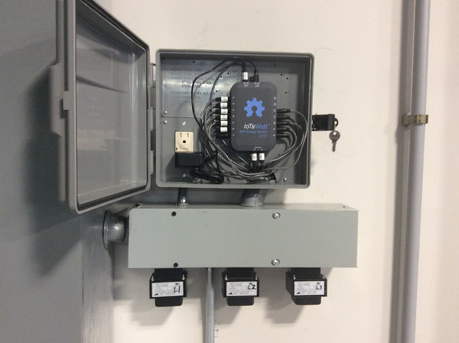
Where I installed an IoTaWatt in a277V/480V three-phase industrial setting, I sourced 277V/12V transformers:
Those three transformers are rated 277V/12V. They weigh a couple of pounds each. I measured the secondary at about 13.5Vrms with 0.2° shift.
So while 9VAC is fairly common in a wall transformer, 12V is arguably more common, and 24V is very common as the historic standard control transformer for HVAC systems. I bring this up because 24V transformers are cheap, usually quite heavy, readily available, and can be easily adapted to IotaWatt.
While the input to IoTaWatt is limited to 15.16Vrms no-load, you can adapt to a higher voltage by simply adding a series resistor of (V - 13) * 1000 Ohms, where V is the no-load rms output of the transformer. By example if you had a nominal 24Vrms transformer that measured 26.5Vrms no load, the equation would be (26.5 - 13) * 1000 = 13.5kOhm. Round up to the the commonly available value which would be 15K.
