Good Morning,
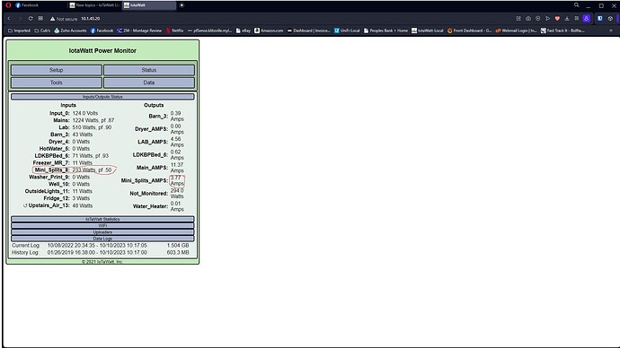
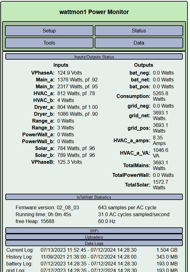
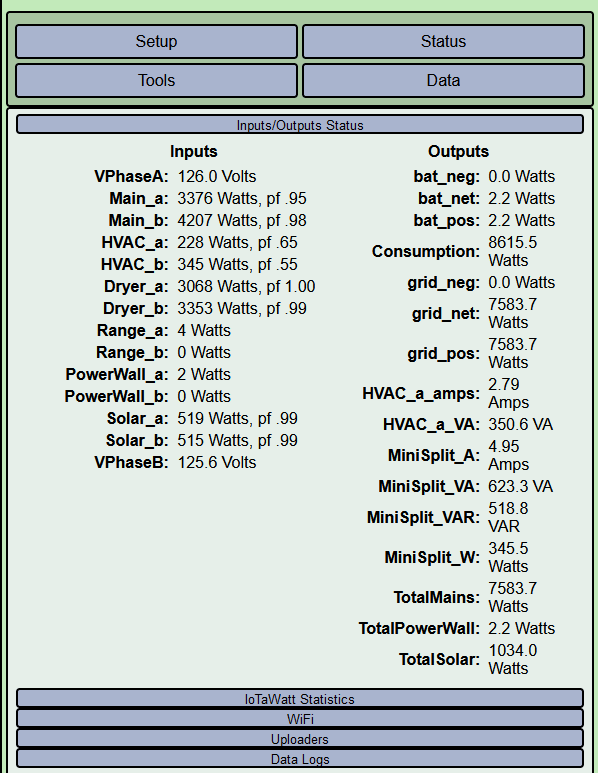
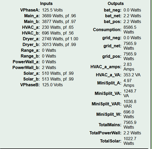
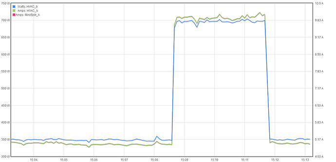
I’ve had my Itowatt a few years now and just installed a couple inverter duty mini-splits heat/air. They are 220 connected to a sub panel and I am measuring both legs to the panel with two ECS1050 plugged into a 3.5 splitter and it plugged into 1 input on the Iotawatt. My amps have always been 2 amps higher. Even when minis-spits are turned off itowatt reports 2 amps. See picture.
Thanks!
I would need a better description of what you are doing to venture a resolution.
Can you post a picture of one of the CTs showing the model please?
I don’t know what a 3.5 splitter is. Do you mean 3.5mm jacks? You say you are measuring “both legs” and have a “couple” of heat pumps. Are you combining 4 CTs into one input?
Are these mini-splits two wire or three wire? Most are two-wire. What happens if you measure only one of the legs?
Big question: Are you sure you have split-phase? True split phase would be 240V. Two phases of a three-phase source is 208V.
Are you sure all of the CTs are in phase? The CTs on different phases must be physically reversed.
Do the mini-splits have pan heaters? That would account for power when they appear to be off.
The power factor indicated in the above picture is very suspect. Mini-splits are usually inverter and operate at much higher PF. If the standby power is pan heaters, I would expect the PF to be near one.
Thanks for replying!
I would need a better description of what you are doing to venture a resolution.
Can you post a picture of one of the CTs showing the model please?
Are these mini-splits two wire or three wire? Most are two-wire. What happens if you measure only one of the legs?
Are you sure all of the CTs are in phase? The CTs on different phases must be physically reversed.
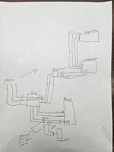
See attached Picture to answer above questions.
I don’t know what a 3.5 splitter is. Do you mean 3.5mm jacks? You say you are measuring “both legs” and have a “couple” of heat pumps. Are you combining 4 CTs into one input?
Two CT’s into one input on the Iotawatt
Big question: Are you sure you have split-phase? True split phase would be 240V. Two phases of a three-phase source is 208V.
Yes-240V
Do the mini-splits have pan heaters? That would account for power when they appear to be off.
Yes, heaters.
The power factor indicated in the above picture is very suspect. Mini-splits are usually inverter and operate at much higher PF. If the standby power is pan heaters, I would expect the PF to be near one.
My concern is I don’t have something hooked up correctly because of the low PF and AMPS are always 2 higher than what calculating watts/volts=amps
I’m going to further investigate this weekend, maybe one or both CT’s are bad. (maybe they were connected without load?)
Watts/Volts does not equal Amps.
Try
Watts / (Volts x PF) = Amps
So I wasn’t taking into account the PF. That explains the amp reading I’m getting. I just need to figure out why these high efficient inverter units are such low PF. Thanks!
I know this is outside the support for the Iotawatt but any suggestions on finding the reason the PF is so low? Wiring or connections cause low pf? Or would it be the design of the unit? Anyone want to chime in on this?
I doubt that 233 Watts is normal operation. Are there any other breakers in that sub-panel? If so, what happens if you turn them off?
What happens if you turn off all breakers in the subpanel except one of the heat pumps, and then the other?
What is the PF when the things are actually running?
The two mini splits are the only items in the sub panel. I raised the temperature and forced one of the units to heat the room up and watts climbed to 2700 with a pf of 93 so I guess there is no issue. Thanks.
Did you figured this out? It’s been a while since you replied but I just installed a new minisplit and I am seeing something very similar…
I have about 1.6A when the unit is off…
But I also only have about 8.6W (need to multiply by 2 because that channel is on 120 and the minisplit is on 220 measuring only one leg of the split phase).
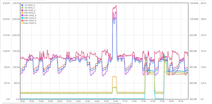
I also noticed the PF being low… so I graphed VA and VAR. I have 183VAR… That is quite a bit…
In the graph below I show my old AC(HVAC_a) and the minisplit (HVAC_b)
It is quite intriguing you also claim 2A even when off… I get the sameish… but most of it is reactive… I am yet to decide if it is a bigger problem for my install (I have solar and power wall… so I need to figure out where that current is flowing as it is loading all my panels).
Can you post a screenshot of your status display with the statistics tab expanded to show the firmware version?
Are you using the “double” checkbox in the setup for that input?
Sure!
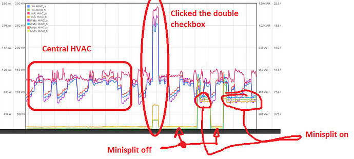
Let me post the same pic with annotations:
I have questions about the double checkbox, see my other post. It multiplies the power by two (which is what I want) but also the current (I think this is wrong, as the CT is measuring the current going into Leg A of the phase and the same current goes out Leg B)…
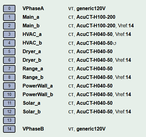
JUST AS A NOTE: I do not think anything is wrong with iotawatt. I think the measurement is correct (I will verify once it stops raining). I am more curious about what the unit is doing to have almost 2A flowing (although it is all reactive power!)
This is pretty confusing. Neither HVAC_a or HVAC_b have double checked.
Here I have double checked for input 9 HWCT004. I don’t see any (X2) on your inputs.

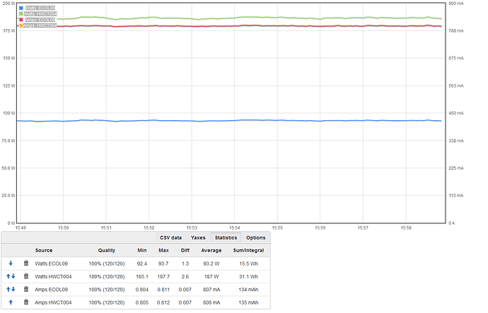
Both are on the same wire, so HWCT004 is showing double the Watts. But notice that they both show the same Amps.

same when you graph (the two Amps plots are on top of each other, you have to look close, but the stats at the bottom tell the story):
Interesting… I see the same. The first image is with no double. The second with double… The problem is only on Graph+
You can see the step. That step was when I clicked the double vs not…
Just confirmed, the minisplit is pulling 5A right now.
I will just go ahead and double them now and double check the current being sent to Influx
…
I remembered why I have not checked on Influx… I changed the server and it is still replicating the data:

been going for like a week… and it seems there are a few weeks to go ![]()
OK, I think I know what’s going on now, and its complicated. The short explanation is that if you set double and leave it alone, Graph plus will show the correct Amps from that point on, but history prior to that will not necessarily show correct Amps.
The Wonky explanation:
The IoTaWatt saves a lot of data on the SDcard. It would be inefficient and in some cases impossible to save everything. So the effective voltage for each input is not saved, but referenced to the respective voltage reference input. For each CT input, the IoTaWatt saves only Watts and VA. To get Amps, VA is divided by Voltage.
When you check double, VA is doubled before it is stored. Mathematically, it doesn’t matter if the Amps are doubled or the Volts are doubled - same result: (2 x A) x V = (2 x V) x A.
Now to get amps, we have to divide VA by the voltage, which in your case is nominally 120. But if we do that, we will get double Amps. So AT THE TIME that you are running Graph+, REGARDLESS OF THE PERIOD BEING GRAPHED, if double is checked, Amps will be computed as VA / (V*2). If double is not checked it will be VA / V. To further complicated things, VA will have been doubled for any time period where you had doubled checked.
I’m sure this is very confusing to everyone. Older versions of IoTaWatt didn’t try to correct for the doubled VA. They simply reported 2x Amps in all Graphs. There were some complaints about that, so the aforementioned logic was implemented. Now we’ve come full circle. It’s Whack-a-mole.
LOL.
Well, I think I do not care. I did not know you are saving VA, Watts and the Vreference… I would have save Vref, and the vector of Amps in relation to the Vref. But that is just me because I like saving as close to possible to the measured variables. Saving Amps and Volts have the disadvantage that the main use case (knowing power) of the product would require a lot of computation.
So, with the “double” checkbox, VA is multiplied by two. Which makes total sense even though not “entirely” correct (not correct in the where V on one side of the phase is lower due to loading, damage, etc).
So when I click double, I am actually saving the correct VA (and Watts which, I care much less about ![]() ).
).
When I do the output for Current:

What happens? Does the correct current gets calculated? The problem is only on Graph+?
Thanks!
The short explanation is that if double is different from when the data was collected, Amps will be wrong. It could be either half or double the correct value. So I recommend being consistent. If you want to use a single CT for a 240V circuit, review the various techniques in the docs. Only “double” is subject to this timing issue.
With respect to Query (Graph+ uses query), all three of those outputs are the same. Graph+ will query with the units under which you select the output.
The specified units are only used by the status display (where Amps should always be correct).
I am now wondering if I should just generate the outputs for Watts, Volts and VA, and compute the rest of the derivatives at the time of saving to the database. I still have not been able to see the outcome of the Double on the data saved on the DB, but I have data that has the Double and not…
BTW, is there any way to figure out the angle of the current with respect to voltage? We (at work) were discussing the fact that my minisplit is always passing ~1A even when off and that all of them are Reactive Power.
My minisplit is an inverter type and we were joking that perhaps they had a lot of capacitance at the input to reduce EMI from the switching power stage… And they ask me “Can you see the angle?” and I do not think I have seen an option or piece of data that saves if the current is lagging or leading the voltage…
It is not useful for almost anything but we are just a bunch of guys doing power electronics being curious… also, current is current and I wonder how that 1A of constant flow will behave with my backup battery when there is no utility…
The angle is +/- arccos(PF). If you want to see the voltage vs current, use the following command to get a set of voltage and current samples for one cycle. You can copy and paste into a spreadsheet and plot to see exactly what is going on. n is the input number to sample.
http://iotawatt.lovel/command?sample=n
The resulting numbers are the ADC readings for voltage and current. The range is +/- 2048 and represents +/- 1.65V. You will need to do the calibration math to relate that back to voltage and current if you need that, but the ADC values should be adequate to show the relationship of current to voltage that you are looking for.
