Any Enphase users on here?

I have another thread where I’ve shown some odd goings on with measuring solar. I have 45 x Enphase IQ7+ Microinverters and I’m seeing some weirdness, I made this new thread so the title can get the attention of other Enphase users

The 4 Solar Circuits go into the combiner. The default CT that Enphase uses is around 1 leg of all 4 of these circuits. I cannot do the same as there is not enough slack in the wire

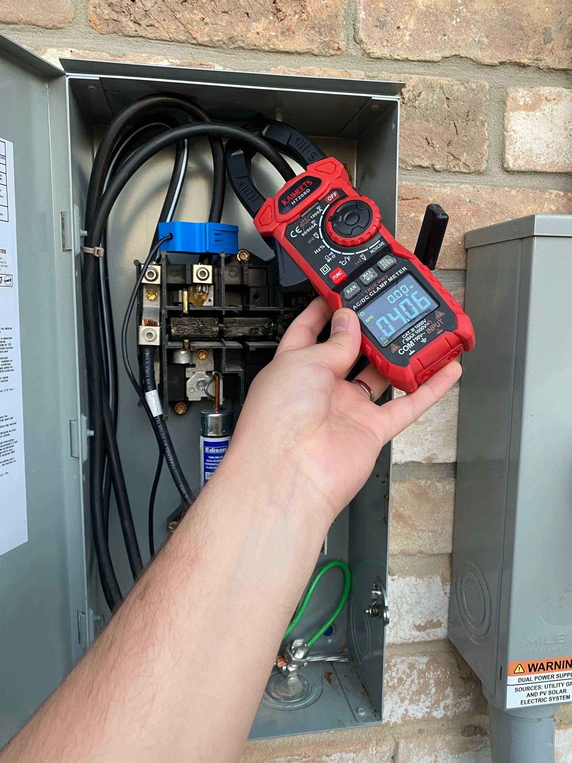
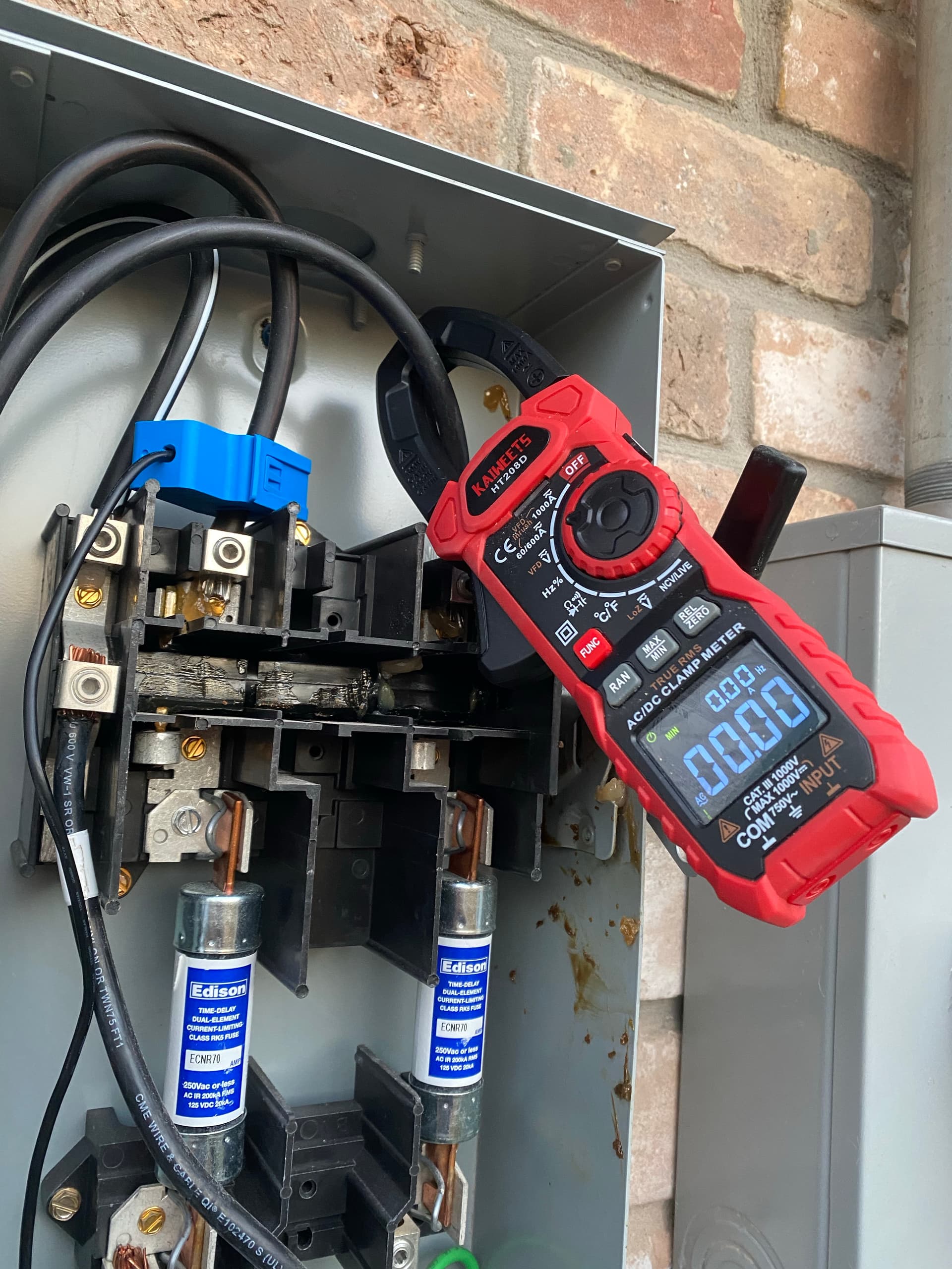
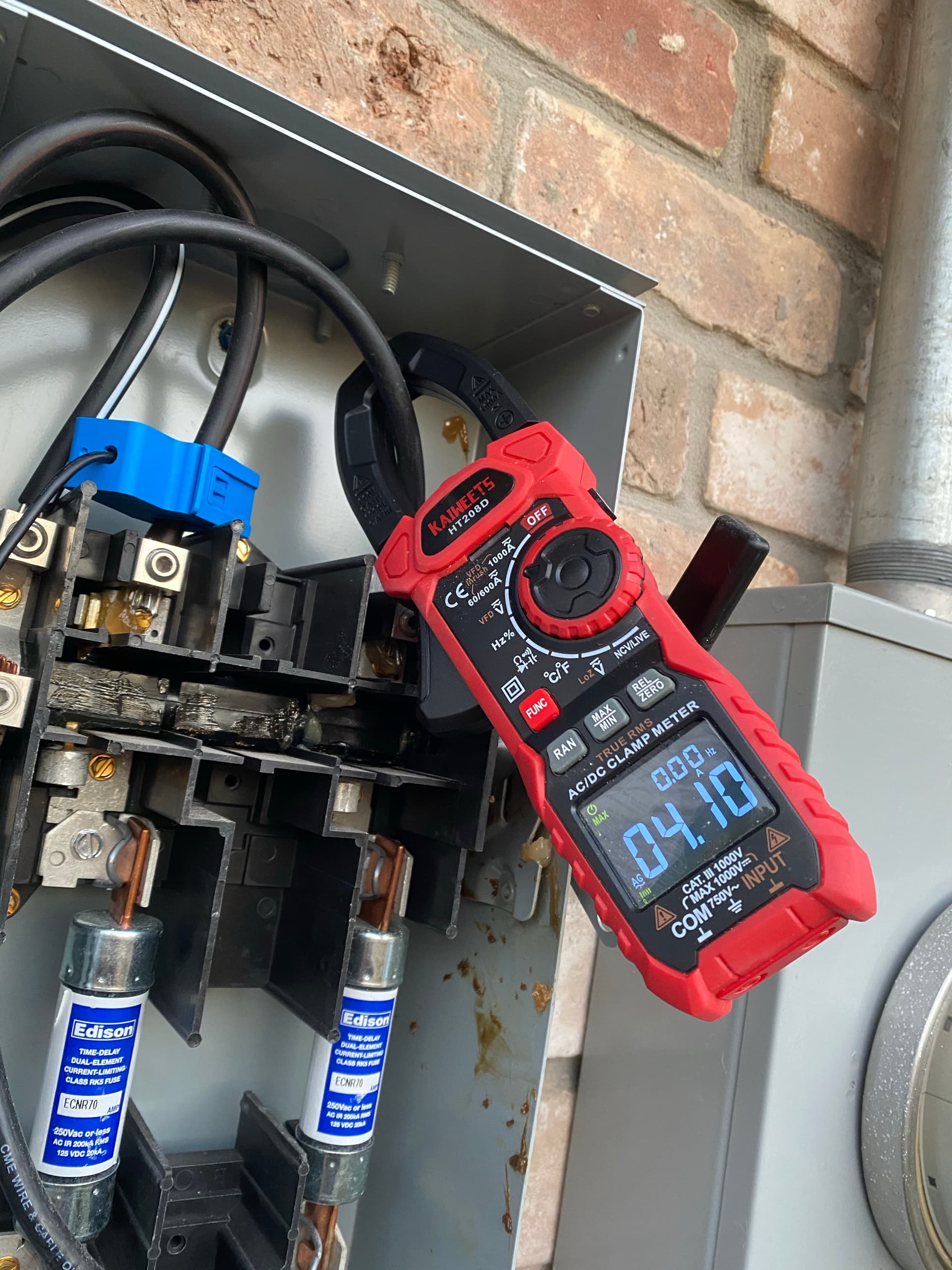
From the Combiner, I have wire that goes into an 80a fused disconnect. This is where I have my CT. I have it on one leg of the disconnect, and have it set to doubled. From there the wire goes directly to a line side tap where its directly connected to the wire coming out of my electricity meter.

Its worth noting there is a neutral in the disconnect. However if you trace it back, the only place it connects is the Envoy itself. So I don’t think measuring it would change the solar measurements, as the panel circuits themselves have no neutral.

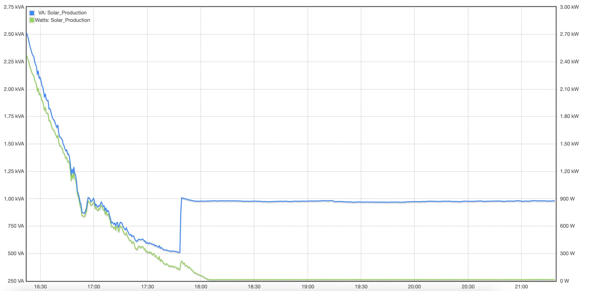
When solar is producing well, everything looks good. The watts chart is fairly smooth, the power factor is 1 which is expected

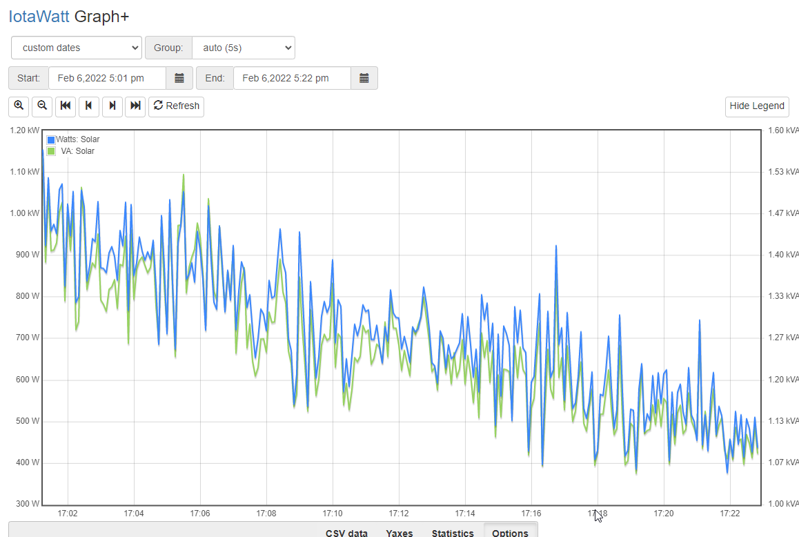
But when production is low, the power factor goes down the toilet, and the chart gets very erratic

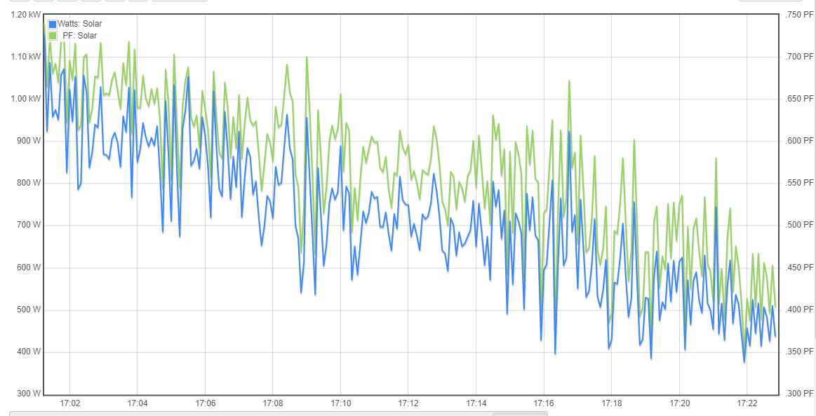
The VA is also completely wrong, which I guess is why the power factor is being calculated weirdly

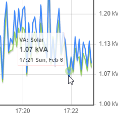
Near the end we have a dip showing 377w

image

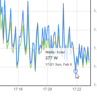
But at the same time, over 1000VA

image

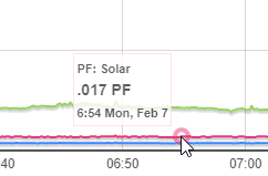
At night its weird too, I get a constant 15w-16w

image

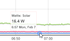
And somehow, almost 1000 VA…

image

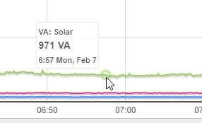
Power factor of course is wrong

image

Is anyone running Enphase Microinverters seeing the same thing?

Today I added a second AccuCT on Line 2, and made sure both were referencing the correct VT, no change

Tomorrow I will try a SCT013 CT and see if there is any difference

I’ve noticed that the CT’s that Enphase is using are the voltage type, not the current type (Forgive my terms if they are wrong). I’m wondering if there is a reason for that

The only difference is that the voltage type has the burden resistor in the CT. I think the “current type” is better because the leads can be extended with no impact on accuracy from small resistance in the extension.

I’m not a power engineer. You could probably get some interesting insight over on the Open Energy Monitor forum.

While most inverter power factors that I see in posts is at or near unity, I’m not so sure that’s optimal for everyone involved. Just a quick search and a little reading was quite insightful as to the interaction of inverter power factor with the grid. It see some inverters can be designed to produce reactive as well as active power.

I’m just guessing but I think the advantage of a unity power factor inverter in a residential installation is that it contributes only the type of power that you are billed for, active power, thus maximizing the savings. The problem is that a lot of such inverters will leave the power company to produce all of the reactive power, which becomes a greater portion of the power they produce and I think lowers the grid power factor.

This article offers what is probably a simplified introduction to the topic. Suffice to say that the more I learn about this stuff, the more respect I have for the engineers that are coping with the existential problems introduced by increasing PV contribution.

Is there any way in IoTaWatt to just tell it to disregard anything if measurements are below 20w?

I don’t mind the pf being a bit “off” of 1 in the day, but when it says I’m making 1kVa at night, its a bit odd

The 15w all night is also throwing off some measurements I’m trying to make by weeding out idle devices

Okay I think I got somewhere, maybe

I threw an AccuCT on L1, but I flipped it. Now I’m getting 10w of consumption which is probably correct for the Envoy etc. Now tomorrow, it should go negative when producing power, which is fine

I’m not too sure what flipping the CT changed though, as I assume it would be same either way

VA still shows 1000 though

Threw on the new CT (SCT013) and no change for the weird power factor and VA, but the wattage seems correct as it did before since I flipped the CT

I checked the spec sheet for my specific microinverters and are they are fixed to being at 1.0. My clamp meter also gets the correct amps every time, unlike the CT’s which show 4a at night

I guess there is just something weird about how the CT’s measure this circuit, very odd

Well, this is interesting. Grabbed a different meter, and tada, 4a!

If I put it on Min/Max, it gets 0 for min, and 4.1 for max

Okay here is the answer from someone smarter than me

This is reactive current due to the capacitance of the microinverters. the phase angle of the current is almost +90 degrees and the real power is miniscule

Unsure if that information leads to anything that could help IoTaWatt in the future “Fix” the reading. The Enphase monitoring system gets it all correct, but given that Enphase engineered that, it’s not surprising

Not sure if there is some funny math they are using there or something

I can confirm that. Measuring with a Fluke True RMS meter, the power factor is consistent with the one reported by Enphase and IotaWatt.

Thanks

So far, I am very happy with how accurate IoTaWatt is. If you look at my posts, I’ve questioned the measurements 4 or 5 times, only to then realize that IoTaWatt is the correct measurement!