Hello! I am interested in getting an IoTaWatt, but wanted to confirm if I will be able to do the installation before I proceed.
I am a software engineer, so am technical, but inexperienced with regard to electrical jargon and functionality, so I apologise in advance for the basic questions.
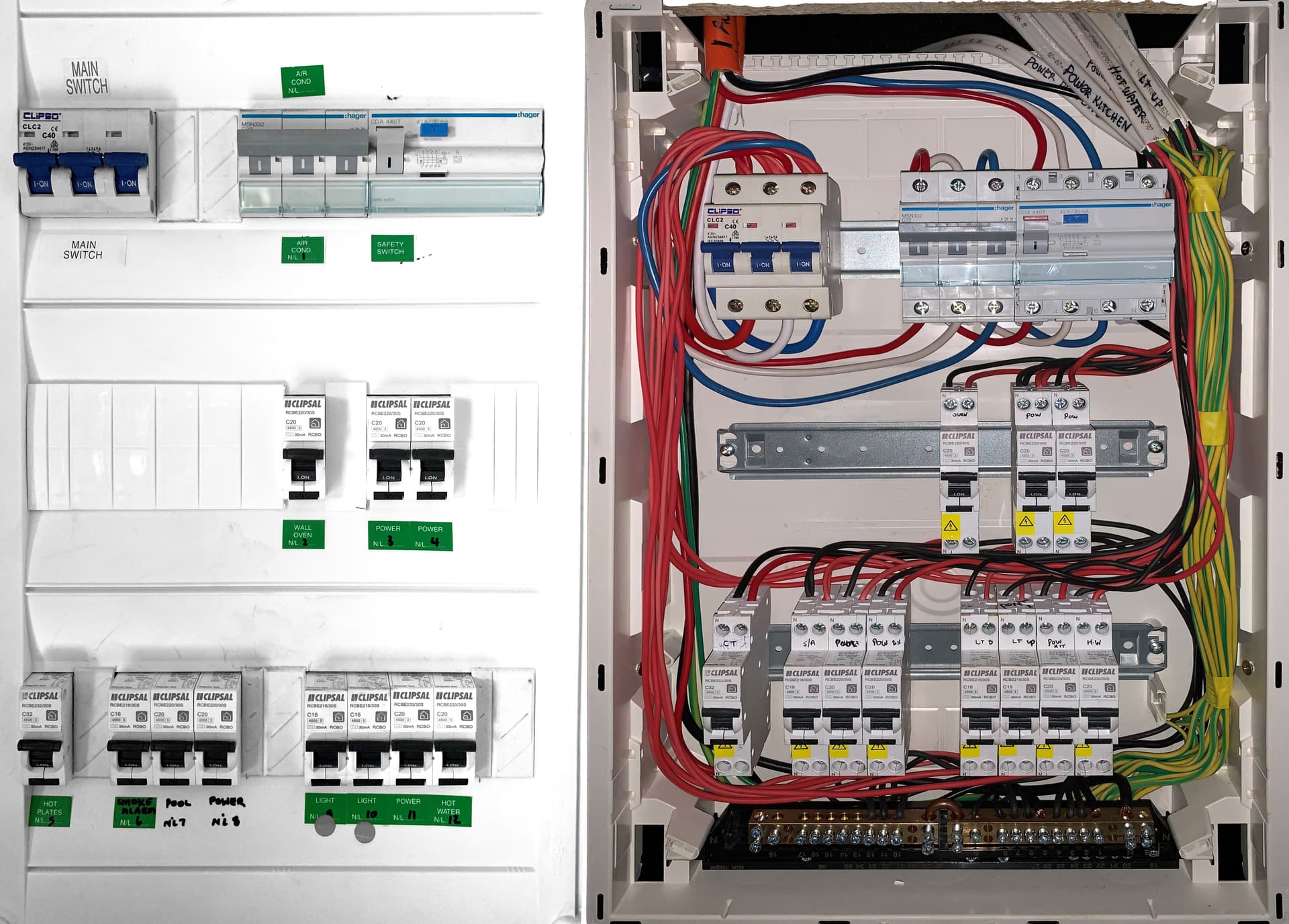
The electrical board in my house (installed in a cupboard in the foyer) is pictured below, with the base cover on and removed:
If I understand correctly, I would be able to monitor everything by getting 14 50amp CTs? I have 3phase coming in and 12 circuits but one looks like it’s dedicated to smoke alarms, which I wouldn’t monitor.
Most of the photos I’ve seen of people’s power boards and CT setups are US based, where the breakers are horizontal and the cables nicely separate with space for CTs. But my board is as shown. So in my case, can 14 CTs be attached correctly at all? With enough space between them? My understanding is that the CTs shouldn’t be in immediate proximity to each other (touching) due to possible interference. I have seen the setups of a few Aussies on this forum as well but they seem to have their powerboards externally to the house, and with very different form factors!?
I know the most elegant/easiest solution would be to get an electrician in to redo/extend the whole board, but costs would be high and I dont want to go down that road. With the board being what it is, could I setup the IoTaWatt successfully or not? If so, I would appreciate a bit of guidance (perhaps marked on the photo) of how one would go about attaching the CTs?
Additionally - if I were to get solar installed one day, does anything get added/changed to this board? I presume not. And that I wouldn’t be able to monitor solar using the IoTaWatt since the solar inverter would be installed outside and away from this unit? What would be my best option in that case?
Looking at the photos there is masses of space for the CTs. I don’t think interference is/will be a significant issue. Think how little space there is in a 3 phase utility meter.
When you install, you will need to take care that the phases are properly identified for each circuit or your data will be incorrect. There are very clear instructions in the documentation on how to do this - it is easy if you follow the instructions step by step.
Iotawatt requires 2 power sockets (one for the voltage reference transformer, the second for power) - if you don’t have those close to where you want to put the IoTaWatt you will need an extension lead or sockets fitted.
IoTaWatt also needs good Wi-Fi signal at the point it is placed.
I count 17 circuits - including the incoming mains.
3 on incoming mains
3 on AC
11 other circuits
So you will need to combine circuits (on the same phase) or do some maths or a combination of the two as you only have 14 inputs on an IoTaWatt. There are other posts here on combining and in the docs (essentially pass two (same phase) cables through the CT.) Or alternatively you can use a headphone splitter and separate (identical) CTs (one is much cheaper than the other - particularly given your board layout).
The Maths element is [incoming phase A] minus [sum of measured loads on phase A] = unmeasured loads on Phase A.
Repeat for phase B and C.
You can move and change CT’s if you want to investigate anything ‘funny’ on the unmeasured loads.
Your incoming appears to be a C40 so 50A CT’s should be ok but you may find that 100A are ok/better - check the accuracy and price over the expected current range. 50A would be fine for the other circuits.
In respect of the Solar - you can only measure what you can connect to the IoTaWatt. CT’s can be extended with headphone extension cables.
If the solar is going to be connected outside of the distribution board you show then you will need another 3 or 6 CTs.
One CT for each phase of the Solar = 3(only one if it is single phase)
One CT for each phase entering the property = 3 (unless you relocate the ones in your distribution board)
Unfortunately 3 phase supply eats IoTaWatt inputs - My solar, heat pump and sub-distribution boards meant I got a second IoTaWatt
I completely missed to count the AC as 3 circuits, so yes that brings the total to 17. The power sockets are not an issue, luckily I have two right next to the board in this cupboard, as well as a couple of network ports. It’s a shame the IoTaWatt doesn’t have wired ethernet.
From an information point of view, combining circuits I think would fine, for example the two wall outlet or the two lighting ones.
Just so that I understand a bit more the concept around same phase - it’s clear about the 3 incoming and the 3 on AC, I can’t combine them, and need 6 CTs for those. But the rest of the circuits, would they all be the same phase or probably not? For example the two lighting circuits? If not, how would I go about figuring out if two circuits are in phase or not?
I reread your post, and think this actually answers my question above - the rest of the circuits could very well be on mixed phases, so I cant just automatically assume to combine the two lighting or two outlet ones? It will be a bit tricky then, as for instance combining “hot water” with “wall oven”, or any two very different functions, isn’t great from a data point of view.
edit: Actually, may not be an issue as I thought. If I use 6 CTs for the incoming and AC, that leaves 8 inputs to be split between 10 of the rest of the circuits (not counting smoke alarms). That should be doable and reasonably accurate from a data gathering perspective…
If you invest in an inexpensive voltmeter, it is easy to determine is two circuits are on the same phase. Simply measure the voltage between the hot (red) conductors. Same phase will be zero, different phases will be 400V. You can also use that technique to associate each of the branch phases with the appropriate mains phase - Red, White or Blue.
Also, given that you will probably be interested in only the total usage of the AC, you can measure the mains (3) and all of the branches (11), then create an output for the AC by subtracting the branches from the main. It won’t be as steady as measuring AC directly, but AC is usually a larger load and the variance should be relatively small.
A voltmeter would do the trick as would - Carefully - following wires as they come out of the main switch Three phase 240v is dangerous - take great care inside your panel and isolate upstream before work inside the panel if it is possible.
I have a test probe - which I use to ‘prove dead’ any circuit I am working on. Search for voltage indicator and proving unit to find one locally. Then follow the ‘prove dead’ protocols you can find on line - It isn’t difficult and is well worth the investment in $ and time to do so.
With your distribution box being bespoke (hand built using breakers and din rails rather than an ‘off the shelf’ 3-phase board) there isn’t the normal labelling that a commercial three phase board would have.
The electrician who installed the board used red ‘live’ cable to feed each breaker from the main switch. You may find that they have grouped the breakers into phases (hence the spacer between them) - if they have then that will make life easier.
Once you have conclusively identified breakers on phase A, B & C I would label them with electrical tape or similar.
Thanks gents, you’ve been very helpful.
This is all new territory for me but very interesting, and learning a lot. Next step is to get the IoTaWatt and get the ball rolling!
Cheers.