Years ago I built my own energy monitor for each phase using an Arduino and that was kind of OK but I never was able to get it that accurate and then something happened that I can’t remember and I decommissioned it. Long story short I am looking to set up monitoring again but want more granularity which is why I am here. Thanks for making a great looking product! Please correct any of my apparent assumptions below!
My situation is that I am in Australia with 3 phase power. My solar inverter just feeds B phase (and I upload to PVOUTPUT). My aircon is single phase. I am an advanced user of Home Assistant so am looking for tight integration with it. I have just installed a power monitor integration which gives me “good enough” info about my power usage with everything that I have a smart switch on (mainly lights some power plugs) so I don’t think I need to monitor my light circuits directly.
If I get a EV then I anticipate using OPENEVSE which will report its own power usage.
Thus I am thinking I need 3x 100A CTs for each of the phases. I am then thinking of purchasing 4x 50A CTs. I would place one on my solar feed. One on my aircon. Then I don’t think I need to monitor each circuit so I would put one clamp around the two power circuits on B phase and same on C phase.
Questions!
I assume with my setup excess solar power flows back out the B phase line. I assume I can work out my total present power usage by A plus C plus either (1) If B negative then solar minus B or (2) if B positive then solar plus B.
I have some CTs from an old Efergy Elite that I used for my DIY system (you can see in the photo). Can I just plug them into the Iotawatt and use them. I know from reading the site that there is a generic option. I also think I read that any CT can be calibrated? Can I I attach the Efergy CT to the same line as an AccuCT and somehow work out the adjustment required to get them to read the same? (Then I could have it moved to its own circuit)
You will see I have ten circuits including the solar feed in. If I change my mind and I do want to monitor each circuit (assuming I get the Efergy CTs to work) could I just have the 100A CTs moved to a specific circuit (I understand it wouldn’t be as accurate as a 50CT) (I have friends who are electricians so no problem moving things as I need)
I assume if I am monitoring the whole phase then I don’t need to monitor every circuit I could do math? For example if I had a clamp on the whole of A phase and the aircon and one light circuit then I know what the remaining light circuit is doing by subtracting the loads on the aircon and light from the total phase?
I assume I can work out what I am exporting by adding A+B+C. Does anyone have any feel for how accurate that is compared to the meter? (1% vs 10% vs ??)
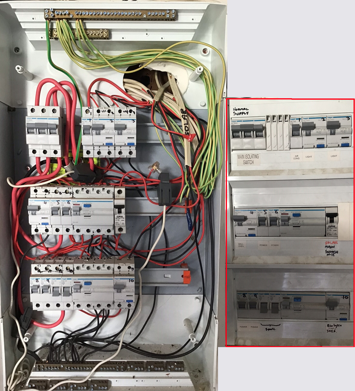
Thanks so much for the advice. I think I know the answers to most of my questions but just want to check. This photo shows my board for reference. The picture on the right is the same thing just showing the labels on each breaker.
Only just received my kit and its not yet commissioned so cant really answer much, though I ordered enough CT’s (3 x 100A and 11 x 50A) to fully populate my box looking to replace the “Current Cost” side of things in my Current Cost/ TPlink HS110/ Node Red/ Grafana setup. Currently I use Node Red to do the calculation diff between my solar and power on one phase but with the different sample periods its not really accurate, just the other day thinking if I run the solar AC feed in the other direction to the main phase thru the CT no maths will be required and I can still graph the solar generation by querying the inverter.
Can you explain this a bit to me. I thought if you are measuring the main wire that the solar is on then you will know you how much are importing or exporting. You say you can also query the inverter for generation so you then add that to the value of import or export for total consumption don’t you?
My inverter is a 10yr old SB5000 that supports connectivity via bluetooth, new ones I believe use wifi so I query its power output every 5mins and populate that figure into a global variable in NodeRed.
The current setup only has 3 CT’s and they are used on each phase so nothing spare for the solar, hence using the bluetooth.
I was planning on keeping up this so as to not waste a CT on the solar feed. Its this 5min solar sampling that clashes with the output from my CurrentCost that spits out data every 10sec or so, hence the inaccuracies.
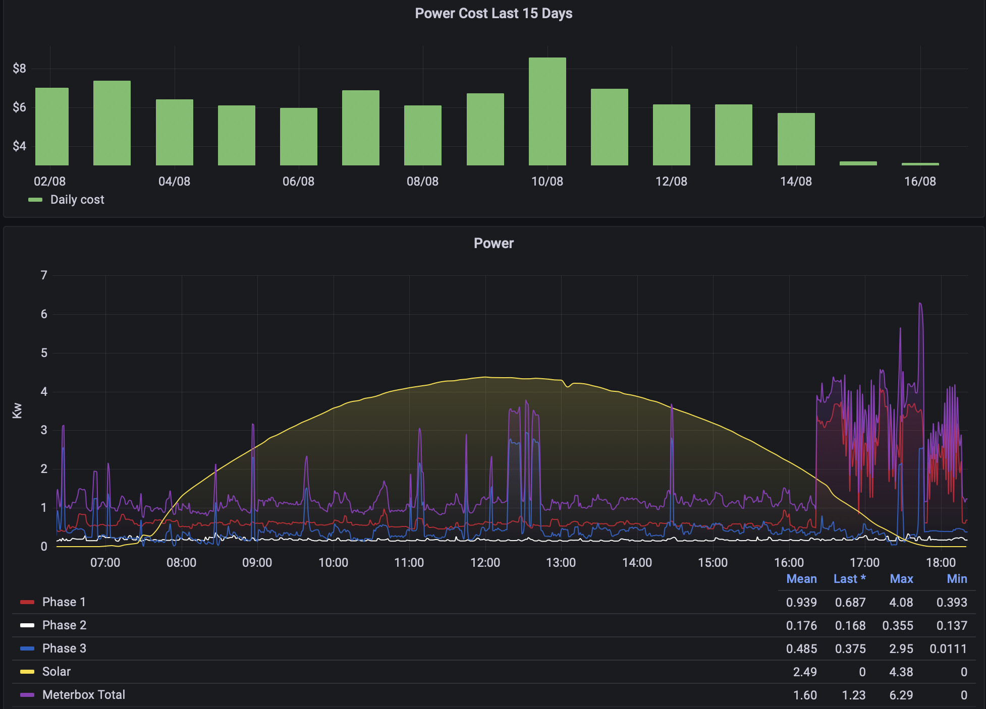
I’ve attached a pic of my Influx/Grafana graphs currently not doing truely accurate calculations of import/export and total cost, that will be revisited when i swap out my old setup for the IoTaWatt gear
Thanks @overeasy . I was also readng here Efergy vs SCT 100 clamp | Archived Forum that they might have internal circuitry that might cause issues? Could they damage the Iotawatt if I tried to use them?
Can I also confirm that there is no issue running two circuits through the one CT?
OK thanks. I am now wondering if I need the 100A CTs for the mains. There is no way I would draw 12000W per phase let alone 24000W! I expect I will get better accuracy with the 50A. I don’t think I will have any issues with cable diameter but I can check that…?
Cost is not the issue when the difference is less than $3! I will check the cable size but as I said it was the accuracy I am interested in but if that is actually not an issue… May as well make sure it is future proofed if additional circuits get added (OPENEVSE for example) so 100A x3 seems the go then.