Australian 3ph Install - Calibrate CT's as?

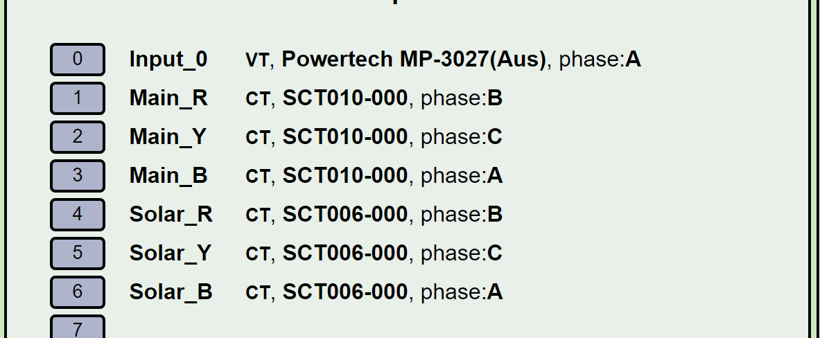
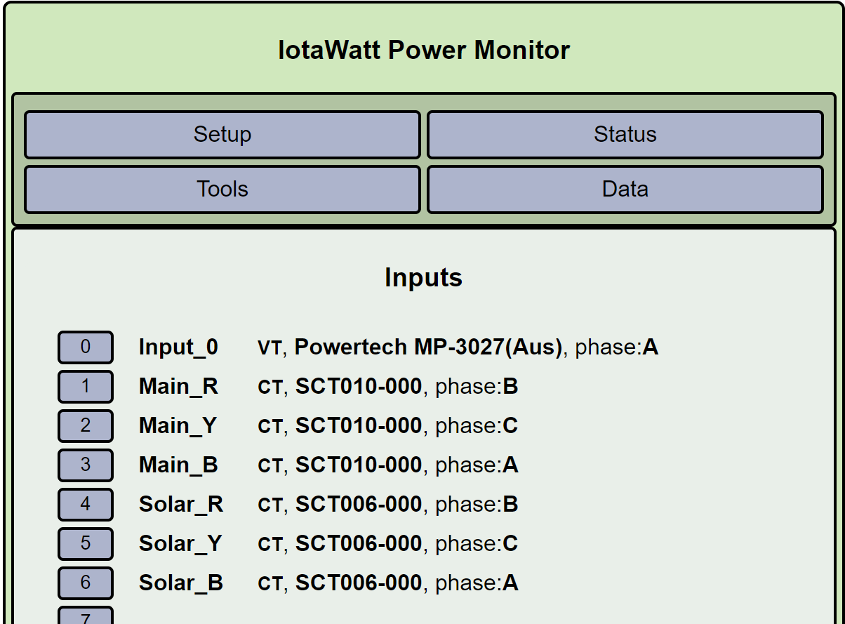
I have setup the iotaWatt energy monitor as per the getting started guide, all good so far. It works and shows up in the Home Assistant integration. 9VAC reading on 220VAC supply calibrated with -calibrated- FLUKE, the AC Adaptor is on Main_B (Phase A) using derived 3ph option.

But…

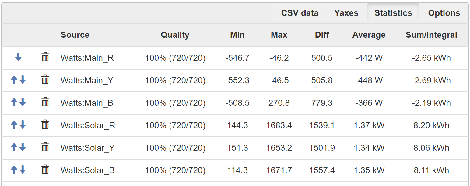
My SolarEdge API gives me an indication of the generated power from the PV system on the roof. On a ‘normal’ day in WA (West Australia) that would produce about 5 - 5.5 kW. However, when reading power indication from the CT’s they indicate about 700 - 800W each, totalling around 2.1 - 2.4 kW on average?

Something similar applies to the calculated consumption as the Home assistant -mistakenly- assumes that solar-production - main export = main consumption which -certainly in my case- is nowhere near the truth. Domestic use is on average very low and even if I test it with everything of it still makes an erroneous calculation for Domestics power use.

So, following summary for setup:

There seems to be a disconnect between what the SolarEdge API says my production is and what I can read form the IotatWatt interface (about -3 kW difference) that is in both directions i.e.;

  • the reading on Solar Power in is lower @ 2 - 2.2 kW
  • also Main Export is lower, @ about 0.8 - 1.0 kW (about 200 - 250 W/channel)

From a usage estimation on domestic use would be < 500W where most power sockets are only connected to 1ph (very odd, but hey welcome to OZ) AC’s are on different phase but not in use.

What could be the cause of the relatively large discrepancy between SolarEdge reported power and indicated power on IotaWatt? As both 3ph channels seem to report low Wattage.

Main Export = about 1/3 - 1/4 of SolarProduction (i.e. prod=700W/channel exp=200W/channel)
Implies domestic use = 2/3 - 3/4 of solarproduction when it is -for sure- nowhere near that…?
The SolarEdge inverter automatically switches of when power generation sinks below 500W, yet the CT’s still give about 15W readout? Can I calibrate that?

Early morning readout when SolarEdge is still off:


(the reverse indicator on B-ph fluctuates sometimes)

One additional question, is there a way to set a threshold value for the Wattage?
I.e. if SolarPower reading on a channel is < 15W report 0W?
I can’t seem to make that work using the Output functions?

It’s hard to tell with the low power draw in the status display above, but it suggests that your setup phase assignments may not be correct. Please review the setup procedure in the docs. Do not take any shortcuts.

There are 36 different combinations of CT orientation and phase assignment. Only one of them is correct. This simple procedure, when followed methodically, will avoid the common pitfalls suffered by those who try to stumble on the solution.

Also, I see that you are using SCT010 CTs. The model tested and parameterized in the IoTaWatt tables is the 50A:50mA model. There are a ton of variations. Please post a picture of your model showing the specs.

Proofing by comparing to your SolarEdge is not the recommended way to do this. Trial and error doesn’t really work well. When you get it right by the docs, you can proof it by comparing the kWh over a period with your meter. I’m confident after that the IoTaWatt will match the inverter metrics.

You should also look into using an integrator to develop import and export to send to HASS.

Hi Bob, many thanks for your quick response, much appreciated!

You are very right with regard to phase settings, after mucking around with the settings I can get the SolarOutput to match with a few kW → ‘noice’ (as they say in OZ… :wink:)

For the SCT010, it may well be that the discrepancy is caused by the model as I am using the below ones:

YHDC
SCT010-B26
80A: 26.6mA
class: 1
sn: 2110-2420

They seem to be indicating low as on average they are indicating -450 - -500W where in reality nearly all the solar production should be going back to Mains as I hardly use anything in the house.
See below snapshot of today’s cycle:

From the ‘tables.txt’ file I can see that the # turns seems to be different?
tables.txt => turns: 1000
datasheet: turns: 3000

Not sure how to work out the phase value nor the p60 & p50 values…
Are the p50 & p60 values the data points from the reference curve on the datasheet for respectively 50Hz & 60Hz?
As per below?

By the way, I determined the reference phase from measuring the ‘positive’ side of the socket of the AC adaptor against each of the phases, Blue = 0 potential hence = reference phase?

i.e. Solar_B & Main_B are same as reference phase for AC adaptor, other two were a bit trickier but tested that by loading each.

Or am I missing something here?

That would result in indicated power of 1/3 actual power.

No, that is not indicating phase shift. The way support is added in the tables is to send me two samples of a particular CT and I calibrate phase correction with an instrument that I custom built. Otherwise it’s anybody’s guess.

You might try configuring them as CR3110-3000 as they are also 3000 turns and have similar shift to the 1000 turns SCT010.