New to this field, but have some experience with monitoring tools.
Am looking for some feedback on my assumptions and kit-out plans.
Context:
I’m in Australia (240v) with a 3-phase supply coming into a meter box which has a feed-out to a small cabin, daisy-chaining to the shed, and then one phase extending up to a small granny flat. Distances are ~ 10-20 metres between each
Main meter box has ONE standard power outlet, which we use to feed an always-on septic system fan / pump.
Cabin has a basic set of circuit breakers, no apparent access to wiring, I believe single phase take-off for this structure, including two hard-wired split-system air-conditioners (both 500W units, I believe).
Next in daisy-chain is the shed, which has 3-phase present (but unused). Hot water (basic element system) I believe is an 1800W element, we have it on a timer arrangement next to the circuit breaker. The switchboard here also feeds in a 10kW solar panel inverter - AIUI it splits feed to each phase equally. We can access the rear of this panel, so TCs will be easy here.
Finally, one phase from the shed up to the granny flat, that feeds domestic devices (1 x air-con, stove/oven (32A), etc). In there we have just another basic circuit-breaker board with no easy access to actual wiring.
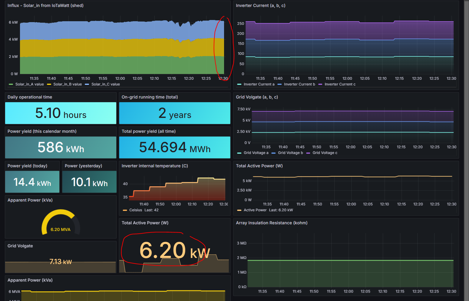
I currently obtain 5-10 minute interval figures for solar power (via Modbus).
We’re using more grid power than I feel we should (20-40 kWh / day), but struggle to reconcile these against solar power, and utilising some wall-plug devices I’ve moved around and run in place for a few days (fridge, computers, etc) to get some average consumption figures.
We get very poor data from our energy provider (1-2h granularity figures, several days lag on availability, manual downloads of xls files).
I manually record daily readings at the meter box for the 3 phases, but it’s pretty unsatisfying / ambiguous of course.
Line drawing of power distribution at the site follows:

Following photos show things better. I’ve had to merge photos as new users can’t embed > 3 images total.
Top - the main incoming meter’s front panel.
Sorry it’s a bit fuzzy - I can update later if needed.
Yellow extension lead at bottom to septic - that’s the socket I’d use for the reference DC adapter.
Middle - this shows the rear of the main incoming meter - from top, incoming from transformer - 4 x black wires (neutral + 3 x phases).
Outbound (bottom) goes to cabin.
Lower - shows the reverse of the main meter board:

Next we have the shed sub-board.
Top – show the front panel - 3 phases, HWS (hot water system) + timer for same. Couple of circuits for 15A and lights within the shed.
Reasonably confident the HWS is the only thing on one of our phases (what the main meter calls #3).
Far-right, the circuit up to the granny flat (‘Roost’ shown here - converted chicken shed).
Middle - the rear of box - showing orange (left, lower, coming up) from solar inverter, and then an insane mess, but at least it looks relatively easy to locate space for CTs
Lower - a slightly better view of the rear of that panel.

Assumptions / questions
I emailed smartguys.com.au recently and received no response - but I gather from other threads that they are indeed still active (as recently as April 2024) and their online store’s stock availability is accurate, so I’ll proceed with purchase via them.
I am thinking I will get two x Iotawatt monitor devices - one to be installed at the main meter, and another in the shed at the sub-board.
I don’t believe there’s a convenient way to measure any of the air-con units, or the single-circuit stove / oven, and am resolved to working out their usage mathematically from other data.
Reference (9V DC adapter) – is this fine to come off the same powerpoint (in main meter box) used to power fan/pump in septic (periodic cyling)?
Do I need a reference DC adapter at both meter boxes (both iotawatts)? I assume yes.
Would it help significantly / much / not at all - to get two more power outputs wired in the main meter box, one per phase, for more reference adapters?
Similarly, with the shed meter box?
Smartguys.com.au only have 100W TC’s on stock but I’d been assuming I’d use exclusively those anyway - mostly for the ability to repurpose in the future.
I gather I don’t lose any significant accuracy with those over the 50W versions (which are out of stock here, and no hint on if / when they may be available again).
Number of TC’s needed - I’m thinking:
4 for the incoming (3-phase + neutral)
4 for solar (ditto)
2 for HWS
6 (2 each) for the 2 x shed internal circuits (‘Power’ & ‘Lights’), and the granny-flat / Roost circuit
Do I need or want TC’s on ‘both sides’ of the incoming meter?
Do I need two per internal circuit - one for neutral, one for active - as I’ve detailed above - or can I start to share ‘common neutral’?