I’m planning to build a submetering system and IoTaWatt has so many attractive features. But I have no coding skills. Is it realistic for me to think I could put something together?
Depends what you want to do. You don’t need to do any coding in the IoTaWatt, and you can get kWh for any combination of circuits using the builtin outputs and Graph+ facilities.
So for instance if you want to see the kWh used on three different circuits (submeters) for the past month, you can simply save a Graph+ that does that. Let’s say I wanted to submeter my heat-pump, my subpanel and my basement circuit:
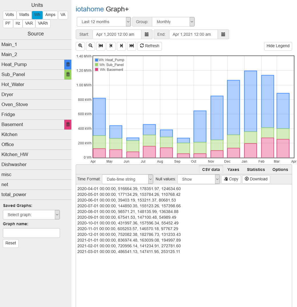
I’m retrieving the Wh used each month on each of those circuits for the last twelve months. I’m displaying the CSV data which has a line for each month including the date, Wh for Heal_Pump, Wh for Sub_Panel, Wh for Basement.
You can change the period covered in the top left, and set the group to daily, weekly, monthly or yearly as appropriate to your needs.
There are ways to upload data to a database and create queries to get the data, but this is about as simple as it gets. You don’t need the cloud. The query to get this graph for the past year takes about 1.5 seconds.
Thanks for the prompt reply. The reason I am leaning toward IoTaWatt is I want remote monitoring but without relying on a company’s cloud servers who could start charging a fee whenever they like. Is that kind of functionality possible out of the box with the right components?
Thx.
Yes, Graphing is included ‘out of the box’ via simple web access direct to the unit. Note that this is not HTTPS (for technical reasons) but it is password protected.
If you are going to do remote monitoring be aware that IoTaWatt requires wifi (and no, it can’t be ‘hard wired’ - again for technical reasons, see other threads on this forum).
For remote access you will need to open a port on the firewall at the installation location and (if not port 80) translate to IoTaWatt in the firewall.
This Video - Home Energy Monitoring with IoTaWatt | Physical Install and Initial Setup - YouTube has an overview of a US installation - the end of the video has how to setup the circuits (as inputs and outputs) and look at the data using Graph+
Thanks for the replies. This is a North American, single (split) phase, 200a 120/240 service. There is a large main panel branching off to 4 sub-panels via one 100a breaker and three 60a breakers. How many CTs do you recommend? A few days ago I would have thought 2 per breaker for a total of 8. But since then I’ve read various opinions – from as little as 1 per double pole breaker (to save money) to 3 per breaker to monitor not only the two 120s but also the neutral.
Also, is there any point in monitoring the 200a mains, if I’m monitoring every breaker in the main panel?
Thanks.
Work out your ‘Why’ - Are you looking at energy usage for fun, to trace the cause of a higher than expected bill, or to change behaviour?
If it is for fun - install what your budget allows, the more the merrier.
If it is to trace a high bill cause then (subject to safety/regs regarding entering your distribution board) you can move CT’s around if budget is tight.
If it is to change behaviour then monitor the high power/use circuits that you have control over (e.g. electric showers) rather than those you don’t (you are unlikely to turn off your fridge).
If you put a CT on the suppliers feed then you can use maths to get the balance of unmonitored circuits e.g. unmonitored circuits = supplier1 + supplier2 - monitored1 - monitored2 - monitored3…
Hi Philrob, I’m setting this up to submeter rental suites so accuracy is important. What I’m wondering is how many CTs I need for each double pole breaker supplying a sub-panel.
Thx.
A sub-panel feed in a split-phase service requires that both of the hot conductors be monitored. That said, you can accomplish that using two CTs, or by passing both conductors through one CT in opposite directions. In this case, I would recommend two per sub-panel for a total of eight. IoTaWatt has 14 inputs, so that is the easiest solution.
If you are monitoring all of the circuits in the main panel, yes you can simply define an output that is the sum of all the circuits and will be the total usage.