Calculating voltage drop as an output

So we use 4 of these units in our school to monitor building power usage and monitor voltage drop. We are in Australia so run at about 230V. Our school has 3 main distribution boards which each feed a number of buildings (we’ll call them A, B, C). Put very basically, power comes in the school into Board A, which feeds a number of buildings and also feeds Board B, which feeds a number of buildings and also feeds Board C, which feeds a number of buildings.

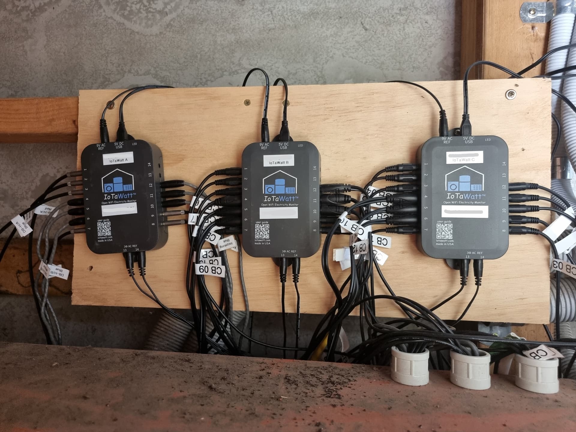
We decided to mainly monitor Board B using 3 IoTaWatt units. We monitor the 3 phases individually, with seperate VTs and CTs for the 3 incoming phases, the 3 phases going to every building and the feed going to Board C also.

After about 6 months of monitoring and some hot days, I’ve been checking to see our voltage drop across the school and checking if it’s within limits it’s supposed to be (from supply to any point in the school). Ideally I need to monitor the voltage near the supply at Board A to compare to (which we may do with another IoTaWatt unit eventually) but realised yesterday that I can calculate the voltage drop using a formula and in my multimeter tests so far, I can calculate what the supply voltage is at Board A using Amps or Watts & PF, the voltage and distance/cable size, I think I could do the same for Board C downstream also.

I’m now trying to enter that in as outputs in one IoTaWatt unit, but my issues are:

  1. The Units option seems to apply to all inputs used in the calculation, but not always. If I choose Watts and use a VT in the calc, it will use the voltage as the number, which is fine. If I choose Amps and use a VT in the calc, it will turn the voltage into a much smaller number (233v = about 0.21 Amps?). Ideally, I want to choose Volts as the Unit because I’m trying to calculate a voltage, but if I do that and use a CT in the calc, it turns the CT into the voltage number instead.
  2. I also can’t use PF in my calculations.

Ideally I’m trying to create this formula:
((Amps of incoming feed phase A * distance in metres * 2 * impedence of cable per km)/1000) + supply voltage phase A

My cable distance is 140m, impedence is 0.089 and assuming the incoming amps is 100 and voltage is 230, if I choose Volts as the Units, it will end up as:
((230 * 140 * 2 * 0.089)/1000)+230
Which isn’t right because the amps is expressed as a voltage instead. If I choose Amps as the Unit, it ends up as:
((100 * 140 * 2 * 0.089)/1000)+0.2
Which isn’t right because the voltage is changed to amps somehow. If I choose Watts, I have to use power factor with watts and voltage to work out amps, but I can’t use PF so I can only average it, but that means it’s not accurate.
((((22000w / 0.9pf) / 230) * 140 * 2 * 0.089)/1000) + 230

Also, using the Amps as a unit, I could almost convert the voltage to the same number by using:
voltage x 1000 - 223.5 x -1.11 + 223.5
Although it doesn’t match perfectly which means I can’t use it, but it’s close.

I know making changes can break existing calculations, but I’d love there to be a way to use different units of inputs in the one calculation. In my case, I need the output to be volts, and I want to use amps of an CT and voltage of a VT in the calculation together. Or if I use watts, I need the output to be volts and I need to use watts of a CT, PF of a CT and voltage of a VT in the calculation.

Am open to any thoughts or suggestions. I also know this may be asking too much and I could just export the data to excel but having an output for this would make it so easy to visualise for any date/time range.

Thanks

Sorry for not responding sooner.

The Script system is intended to allow combining inputs to aggregate or disaggregate measurements. Each input, depending on if its a VT or CT, has associated with it a number of measurements. There is no method of expressing, internally or externally (syntax), which of the various measurements for a given input is to be used in a particular use of that input. The unit associated with the expected output is used.

VTs and CTs have uniquely different datalog entries. VTs save Volts and Hz, while CTs save Watts and VA. Volts and Watts are stored in the same place as are Hz and VA. That’s why you get Volts when you use a VT in a Watts calculation. The situation with amps is a little more complicated but is nevertheless a result of the same situation.

Stepping back, the IoTaWatt has a decent single processor, but it’s not without its limits. The processor spends 67% of it’s time strictly measuring voltage and power. That leaves 33% to do everything else, including running a web-server, uploaders, managing the datalogs, message log. The processor also has other resource constraints like program and data memory that restrict how much it can be programmed to do.

The design philosophy is to simply and accurately collect the data and make it available, through uploaders and APIs. Processing that data beyond basic collection is left to an external process. So to do what you want, you can export all of the relevant metrics in their native units to Emoncms, PVoutput or something like NODEred and perform those calculations.

As an aside, I would offer that you only have one real variable in the calculation, which is current. Temperature is also a second or third order parameter. Moreover, if you are getting the resistance values from wire tables, I can tell you that in many cases the resistance of a circuit can be affected by the various connections. Also, and probably most significantly, with three-phase, the current is probably not traveling strictly through a circuit of the phase main and neutral. In all probability, the majority of it is traveling through the other two phases. Only the net difference should be traveling through the neutral, which is probably very little.

What might make more sense and be quite a bit simpler would be to empirically measure the voltage drop with two observers and record the phase current on multiple occasions so as to obtain a data set that can be plotted as voltage drop vs current. I believe you will find it to be a more-or-less linear relation. Then you can use the slope of that function in an output with current to determine an estimated voltage drop.

Or you can add another sensing device to the A and C service and upload them all to, say, Emoncms.org to get a more precise answer. I think the cost to use Emoncms.org is something close to $1/measurement/year.

EDIT: You indicated that you have a fourth IoTaWatt. That could be setup to monitor either the A or C voltage for at least one phase. The resulting timestamped data can be output as a CSV table using Graph+ or query, and a corresponding table covering the same time period could be produced at the B location. The two can easily be put into a spreadsheet to plot and otherwise analyze the relationship, particularly if you also output the corresponding Amps at the B location.

Thanks for all that. That’s good info to think about. I will probably end up getting another 1 or 2 IoTaWatt units to monitor voltage at the two seperate locations, that will end up being the most accurate info, particularly because we also have Solar which does boost the voltage on 2 phases at Board B and because of the other reasons you’ve mentioned. I’ve been working on uploading data to somewhere central but I have to work within the bounds of the network at the school. I may end up trying to run something like Econcms locally but it’s a project for when I have more time. For now, I appreciate the insight into what I should/shouldn’t expect from the on-board processing (I knew it was pushing it a bit) but I’m still very thankful for the amount of data these little units have given us. The fourth unit is monitoring a single building to measure future capacity.

Thanks again, if it’s interesting, here’s a photo of our main monitoring setup:

1 Like