Calibration of CT

Well, I finally got around to installing the 2nd IoTaWatt. I have had an ECM1240 for many years and it is time to replace it with something better. I have a bunch of Micro40 CTs.

These are listed as 26.23mA @ 40A

This looks like a turns ratio of 1525.

So I put one on my HeatPump Water Heater. I also put a ECOL09 on the line and connected it to another input. In order to get the pf to match, I had to set the phase to 5.00 degrees to get the two channels to match. Since both CTs are solid core I would not expect it to need so much phase offset.

If I send you one, will you put it on your calibrator?

Solid cores are a PITA but low power not so bad as I don’t have to wind them up too much. Sure, send me one and I’ll test it.

Phase shift in a CT is not a constant. It’s a function of current. Typically it’s pretty constant in the middle/high end of the range, but higher at the low end. This is all complicated by the diminishing accuracy of my calibrator at the low end. Here’s what an ECOL09 looks like:

image

It is unlikely that this other solid core has a phase correction of 5°. I don’t think I’ve ever tested one at more than 1°. I’ll take a look and see if I get similar results. Out of curiosity, what was the PF when you compared them?

The latest release, just out today, has an improved phase measurement algorithm. You might try measuring the phase difference with that vs your VT for both CTs and comparing that result.

iotawatt.local/command?vtphase=n

where n is the input channel of the CT. While the actual phase difference is only valid for pure sine waves (unity power factor), it is essentially the same formula as power-factor. If you water heater also has a resistance mode, as many do, that would be another lore reliable data point.

Here is a picture:

hpwh50 is with the ECOL09

I’ll compare another circuit with a purely resistive load.

Okay, I tried it on my heated floor. It is rated at 1000W and that is what I see with both a Micro40 and ECOL09 (within a watt or two, which is well within the stated accuracies of the two CTs).

I see this on the Micro40 channel
Sample phase lead

Channel: 9
Refchan: 0
Measured shift: 33.88 degrees
Artificial shift: 33.70 degrees (60) samples
Net shift: 0.18 degrees

And this with ECOL09:
Sample phase lead

Channel: 3
Refchan: 0
Measured shift: 32.37 degrees
Artificial shift: 33.75 degrees (60) samples
Net shift: -1.38 degrees

These numbers seem pretty consistent and don’t seem to vary when I adjust the phase lead. If that really is the case, it would see to indicate that I should use 0.2 for the Micro40. But, it would see that the ECOL09 should be using something other than the 0.3 it is using. Or, am I not understanding the numbers printed?

Those numbers are the uncorrected shift relative to your VT. So the Micro 40 leads the VT by 0.18 and the ECOL09 lags the VT by 1.38. The net difference says the Micro leads the ECOL by 1.56. Since we know that the ECOL09 is about 0.2, that puts the Micro at about 1.76.

I think you ar3 60Hz,so thatshould be pretty close. Your VT is then about 1.58.

Don’t know about the water heater PF matchup. Would need to see the numbers.

EDIT: Got ahead of myself and didn’t see your other previous posts. Couple of things.

You are on 02_03_20. The latest ALPHA 02_03_21 Has the improved phase shift algorithm. I don’t expect a huge difference, but it is more consistent and repeatable to another decimal place.

I see the PF difference. At two decimal places, those could be .934 and .935. I doubt they are a full .01 different.

Okay, makes sense. I set the Micro-40 to 1.52 degrees, since the numbers vary some and that seems like it is probably closer. With that, the two channels are within 1% of each other. The PF is now listed as 0.95 for the Micro-40 and 0.94 for the ECOL, but as you said they could be closer due to the rounding (but I doubt that they really are as close as 0.945 and 0.944, due to the stability of the numbers).

Won’t know unless I test, but it’s possible that the Micro has a lot more shift at 400 Watts than at the 1000 Watts you used for the measurements. It gets to be a black art at the low end.

Where should I send the CT to test?

Package is on its way to you. USPS says it should be there on Saturday. Thanks for taking a look at it.

I have some early indications on split-phase voltage matching. I have two IoTaWatt devices, so I put one on each leg/(not really a phase, since it is 180 degrees off instead of 120 like in three phase). I calibrated each of them using a Fluke 87V meter. Over a period of time, I have been able to see that they can differ by as much as 2V. The difference varies with local load differences as expected, but sometimes even when the loads are fairly equivalent. Now, there is a normal fluctuation of the voltage, over several volts, during the day/night. Before the major storm, those had gotten much tighter (50% of what had been normal). But after power was restored, the fluctuations have returned to their previous higher amount. It’s kind of interesting to see.

I think you have done a great job with this project and I am looking forward to getting more use out of it.

I took a look at the split-phase voltage issue awhile back. I think it was when I was still participating in the OEM community. What I came to believe is that, while also a polyphase problem, it’s quite a bit different from the three-phase problem.

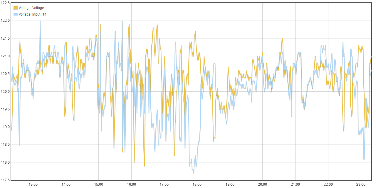
I had hooked up a second VT to my other leg for a few weeks. Not sure how accurately I callibrated the second VT, but stare at this for a minute until it starts to make sense.

Taking the big view, the two seem to pretty much go up and down together. I’m on a shared transformer. There are 6 other houses contributing to the load. A characteristic of the US split-phase power system is that larger loads are typically 240V. In other words, they effect both legs equally. So as the collective load of all of the houses goes up and down significantly, it should be these larger appliances like water heaters, clothes-dryers, and ranges (not to mention electric heat but I don’t believe there is any here). So they cause both legs to vary. This works well when the voltage of one leg is a proxy for the other.

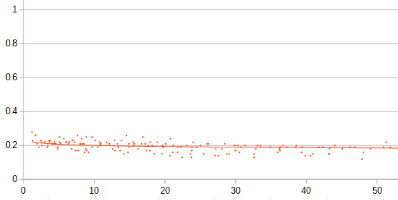
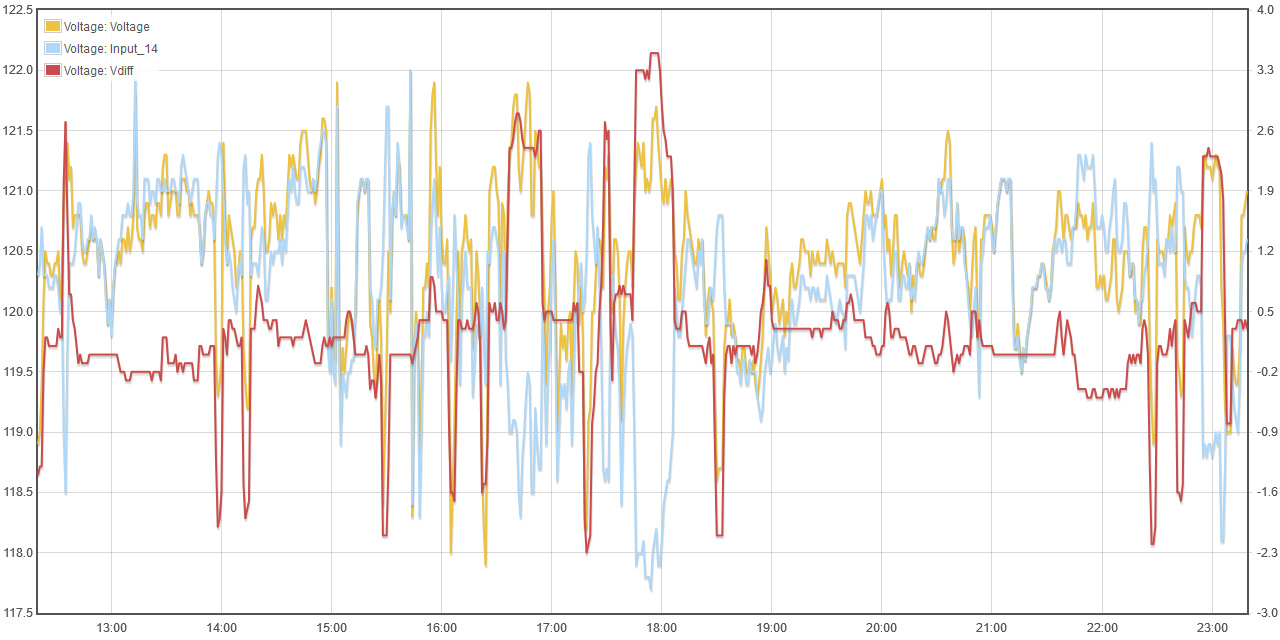
I just created an output that is the difference between the two legs and added it to the graph with the right side scale:

You can see that for the most part, the difference between the two legs is in a small range of about +/- 0.5V. That’s not too bad at all. But what about those spikes? I’ve got data here to explain them.

When there is a transient large difference, I believe it’s because of an imbalance between the two legs - a large 120V load. That causes current to flow through the neutral wire back to the transformer. The voltage drop across that neutral wire increases as the current increases. My neutral is probably 250 feet long, aluminum wire. It has resistance.

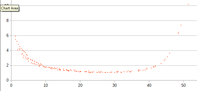
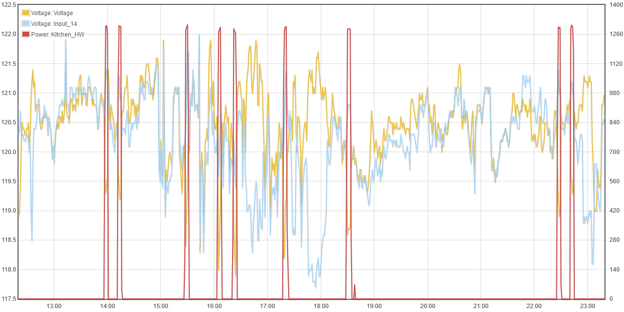
So lets test that out, notice the prominent places where the “voltage” leg drops, and the “input_14” leg goes up. Now look what happens when I add a 1200W 120V booster water heater to the plot:

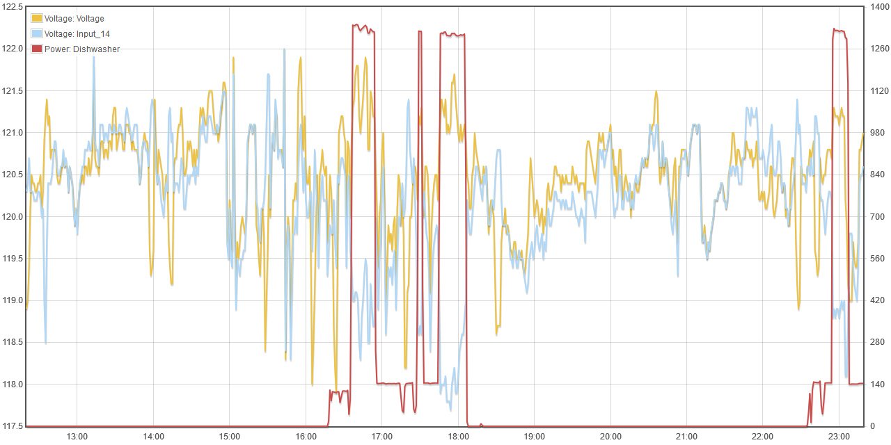
I think that accounts for just about every one of those dips. What about the excursions the other way? My dishwasher has a 1000W+ temperature boost that uses 120V:

So you can see that for the most part, the larger loads that naturally use 240V do not have much of an effect on the reliability of doubling one leg to get total voltage. It’s a self-correcting system. When medium power appliances are used locally, they can cause a larger variation, but it’s usually transient and a small part of the overall story. I see no evidence at all of my neighbors’ 120V loads, because it’s all about their neutral wire to the transformer.

My conclusion is that unless your panel is heavily loaded and out of balance, the single VT reference is as fine. That said, when version 4.9 of the IoTaWatt comes out in a few months, you will be able to add another VT for the other leg and use that for the reference on those circuits.

EDIT: I dug up this data from Oct 2017 using the history and graph features of my home IoTaWatt. I had only collected this data for a couple of months, but it was still there, and I was able to also create the voltage difference output today and plot it with that historic data. The water heater and dishwasher as well as all the other inputs are all still there too, and should be for a decade or more.

I am in complete agreement. While using a single reference voltage and calculating power this way would not be suitable for determining revenue for an electric company, it is generally fine for many other uses. You are also correct that a voltage difference between the legs can only really be caused by unequal loading and the resistance of the wires. My numbers are similar to yours. I have few large 120V loads: heated floor, microwave oven, furnace. The microwave doesn’t get used frequently, but the other two do. But, as you said they don’t have that much of an impact on the numbers (unless you are a utility company responsible for revenue :wink: )

Since I wanted to be able to get more detail on what is using power in my house, I wanted more channels. Since I now have two IoTaWatts, I have to have two reference channels, so I figured putting them on different phases would make more sense.

But, it has also complicated things too. Previously, I used a single CT for my 240V loads (pumps and water heaters). Now, to do the math for Other correctly, I need measure both legs and dedicate channels for that. I have four loads (while 5 if you count the fire sprinkler pump, but that should never run). Since the well pump and the septic pump are both 2HP pumps, their signatures are very similar so combining them will make it hard to get the data I want. The two water heaters are a little better, since one has 5500W elements and the other has 4500W ones and typically draws 400-500W on the heat pump. So, under 700W means the heat pump is on. ~5000W means the heat pump and one of the elements of it are on. 5400-6000W means the heat pump and one of the elements from the other heater are on. Finally above 10000W means both heaters are on along with the heat pump. But, I am probably going to put the HPWH and the Septic pump on the same channels and the regular WH and the well pump together. Still only using 4 channels for the 4 items, but should be able to tell the health of all the items and (with some extra math) get the power utilization for the individual items.

As you can imagine, that is a lot of power. While my generator can handle that, it probably would struggle with that plus one or more of the pumps and the water heater in the barn. So, one of my goals for the system is to prevent that from happening. I believe MQTT and NodeRED is the way to do that, but I can probably achieve it with NodeRED and influxdb.

Hi Neel,

I got the Micro40 yesterday. Cute little thing. Ran the calibrator on it and here’s what I got:

image

The Y axis is phase shift, the X axes is primary current. This is consistent with the field measurements that you did. The HPWH was very low amperage, and 5 degrees would be about right. The heated floor at 1000 Watts gets down closer to the 1.76 that was measured.

This is not really something I would use with IoTaWatt. When I get the new calibrator built, I will be able to test with a lower value burden resistor. I think that’s the problem. With that little core, it just can’t push the VA needed for a 24 Ohm burden resistor. On the other end, it starts to climb at about 30 Amps, which indicates to me that there is some distortion starting. Again, it would probably work OK up to 40 Amps with a very low burden resistor, but not with a 24 Ohm, or 20 Ohms that newer IoTaWatt use.

So I would advise against using these with IoTaWatt.

Thanks for the testing. Did you get an indication of the current accuracy and the turns ration?

When I bought them, there were not the choices that are available today. They are rated for up to 40A, but I never used them on anything larger than a 30A circuit. That variable phase shift makes them unsuitable for circuits that have a diversity of current/power draws, but they might be acceptable for some circuits.

Well, I had already set up my HPWH with an ECOL09 on one leg so, I compared it to the micro40 on the other. Despite the pretty poor phase shift, the two are tracking well. The accuracy spec on the micro40 is 3%, and I would say it generally meets that. Now I have to decide if I want to really replace them or not. My panel uses 1/2 height breakers (only 1/2" wide) so the micro40 is a better fit, size-wise.

The turns ratio for this one sample is 1528 across the full range from 0-40A. Understand that these may have completely different phase characteristics with a much lower burden resistor. IoTaWatt uses 50ma max input with a 20 Ohm burden, which equates to 1V input (2.82V peak to peak). Many quality power meters use .33V, and so they use a burden that is much lower than IoTaWatt. The Brultec probably does that, and these might have acceptable phase shift when used with their monitor.